Do you have a question about the Sutter Instrument MPC-200 and is the answer not in the manual?
Electrical safety guidelines and precautions for operating the MPC-200.
Operational precautions and warnings for safe and correct system use.
Safety precautions for handling sharp micropipettes.
Overview of the MPC-385 Series documentation structure.
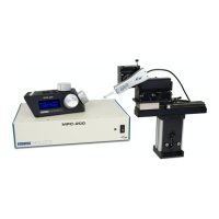
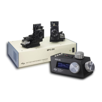
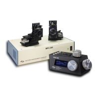
Lists all components included in each MPC-385 system.
Guide to connecting the system and initial power-up procedures.
Explanation of white buttons, black switches, and other controls on the ROE-200.
Details the power switch and DIP switches on the MPC-200 controller.
Instructions for mounting the MP-285/M to a stand using the adapter plate.
How to adjust the angle and exchange pipettes.
Procedures for mounting various types of headstages.
Techniques to reduce electrical noise interference.
Specific instructions for non-standard installations like right-angle adapter.
Initial steps for using the system, connecting power and powering on.
Core operational procedures, initialization, and display screens.
Procedure for setting a specific work position using the WORK POS function.
General overview, VCP settings, protocol, handshaking, and command formatting.
Parameters, microsteps/microns conversion, travel speed, and specific movement commands.
Commands for checking device status, firmware, position, and changing active device.
Guidelines for routine cleaning and inspection of the system.
Technical specifications for the MP-285/M manipulator.
Technical specifications for the MPC-200 controller.
Technical specifications for the ROE-200 input device.
Quick summary of manual operation controls and functions.
Quick reference for configuration switch settings.
Quick summary of external control parameters and protocols.
| Number of Channels | 2 |
|---|---|
| Output Voltage Range | ±10V |
| Travel Range | 25 mm per axis |
| Power Supply | 100-240 VAC, 50/60 Hz |
| Interface | RS-232 |