MPC-385 SERIES OPERATION MANUAL – REV. 3.21K (20201120)
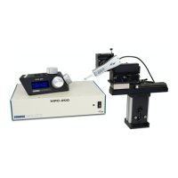
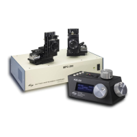
2. MPC-200 MULTI-MANIPULATOR CONTROLLER AND ROE-200
INPUT DEVICE OPERATIONS
2.1 Electrical Connections and Initial Operating Instructions
Initially, you may want to simply connect the two manipulators, the controller, and the ROE
together and try some gross movements in order to get a feel for the controls and how to
make simple movements. It is perfectly acceptable to set the manipulators in the middle of a
bench top, make all electrical connections and then observe each unit’s movement by eye.
Even if you wish to directly install the manipulators in your rig, it is useful to follow the
initial setup procedure to learn how to move the units to allow easy access to the mounting
screws.
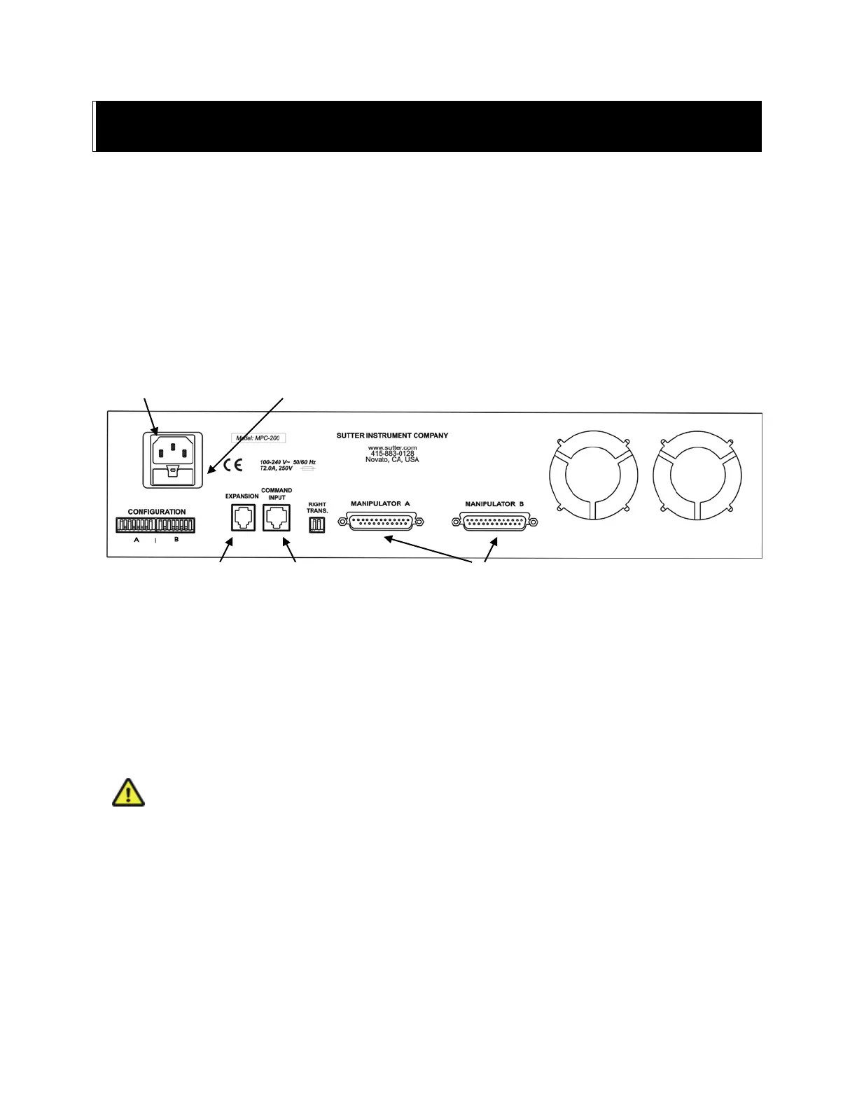
1. Connect the power cord to the power entry module on the back of the MPC-200 controller.
Figure 2-1. Rear of MPC-200 controller cabinet.
2. With the power OFF (front panel switch in the “0” position), connect the ROE-200 input
box to the MPC-200 controller using the RJ-45 8-conductor cable.
* Use the
CONTROLLER output on the back of the ROE and the COMMAND INPUT on the back of
the controller.
3. With the power OFF, run a DB-25 cable from each of the two MP-285/M mechanicals to the
DB-25 connectors marked “MANIPULATOR A” and “MANIPULATOR B” on the back of
the controller.
*
* CAUTION: Never connect or disconnect the ROE or the MP-285/M while the power is
on!
2.2 Initial Operating Instructions
After all connections are made, power up the MPC-395 using the 0/I switch on the front of
the controller. As it initializes, you will see a startup screen on the ROE-200 that briefly
displays the name of the device and the version of the installed firmware. As the power
switch is the only control you will need to access on the MPC-200, the controller can
ultimately be placed in an out of the way location (e.g., under your bench).
DAISY CHAIN SECOND
CONTROLLER