66
MPC-385 SERIES OPERATION MANUAL – REV. 3.21K (20201120)
physical Origin position is fixed at beginning of travel (BOT).
This means that all higher positions (towards end of travel
(EOT)) are positive values; there are no lower positions and
therefore no negative values are allowed.
7. Absolute vs. Relative Positioning: Current position (‘c’) and
move commands always use absolute positions. All positions
can be considered “relative” to the Origin (Position 0), but all
are in fact absolute positions. Any position that is considered
to be “relative” to the current position, whatever that might
be, can be handled synthetically by external programming.
However, care should be taken to ensure that all relative
position calculations always result in correct positive absolute
positions before initiating a move command.
Declaring relative position variables in C/C++:
/* relative positions for X, Y, & Z */
double rp_x_um, rp_y_um, rp_z_um; /* microns */
/* initialize all relative positions to 0 after
declaring them */
rp_x_um = rp_y_um = rp_z_um = 0;
Enter any positive or negative value for each relative position (e.g.,
rp_x_um = 1000; rp_y_um = 500; rp_z_um = -200 … etc.
For each axis, check to make sure that the new resultant absolute
position (to which to move) is within bounds. Reset the relative
position to 0 if not. If relative value is negative, its positivized value
must not be greater than the current position. Otherwise, if
positive, adding current position with relative position must not
exceed the maximum position allowed. If out of bounds, resetting
relative position to 0 allow the remaining conversions and
movement to resolve without error.
/* check to make sure that relative X is within
bounds */
if ( ( rp_x_um < 0 && abs(rp_x_um) > cp_x_um ) ||
(cp_x_um + rp_x_um > max_x_um) ) /* out of
bounds? */
rp_x_um = 0; /* yes, so reset relative pos. to
0 */
Repeat the above bounds check for each of the remaining axes.
For each axis, calculate new absolute position in microns and then
convert to microsteps before issuing a move command.
/* convert X relative position to absolute
position */
sp_x_um = cp_x_um + rp_x_um; /* add relative pos.
to current pos. */
/* convert new absolute X position in microns to
microsteps */
sp_x_us = sp_x_um * um2usCF;
Repeat for each of the remaining axes as required before issuing a
move command.
8. Position Value Typing: All positions sent and received to and
from the controller are in microsteps and consist of 32-bit
integer values (four contiguous bytes). Position values in
microsteps are always positive, so data type must be an
“unsigned” integer that can hold 32 bits of data. Although
each positional value is transmitted to, or received from, the
controller as a sequence of four (4) contiguous bytes, for
computer application computational and storage purposes
each should be typed as an unsigned 32-bit integer (“unsigned
long” in C/C++; “uint32” in MATLAB, “U32” in LabVIEW,
etc.).
Position values in microns (micrometers or µm) should be data
typed as double-precision floating point variables (“double” in
C/C++ and MATLAB, “DBL” in LabVIEW, etc.).
Note that in Python, incorporating the optional NumPy
package brings robust data typing like that used in C/C++ to
your program, simplifying coding and adding positioning
accuracy to the application.
9. Position Value Bit Ordering: All 32-bit position values
transmitted to, and received from, the controller must be
bit/byte-ordered in “Little Endian” format. This means that
the least significant bit/byte is last (last to send and last to
receive). Byte-order reversal may be required on some
platforms. Microsoft Windows, Intel-based Apple Macintosh
systems running Mac OS X, and most Intel/AMD processor-
based Linux distributions handle byte storage in Little-Endian
byte order so byte reordering is not necessary before
converting to/from 32-bit “long” values. LabVIEW always
handles “byte strings” in “Big Endian” byte order irrespective
of operating system and CPU, requiring that the four bytes
containing a microsteps value be reverse ordered before/after
conversion to/from a multibyte type value (I32, U32, etc.).
MATLAB automatically adjusts the endianess of multibyte
storage entities to that of the system on which it is running, so
explicit byte reordering is generally unnecessary unless the
underlying platform is Big Endian. If your development
platform does not have built-in Little/Big Endian conversion
functions, bit reordering can be accomplished by first
swapping positions of the two bytes in each 16-bit half of the
32-bit value, and then swap positions of the two halves. This
method efficiently and quickly changes the bit ordering of any
multibyte value between the two Endian formats (if Big
Endian, it becomes Little Endian, and if Little Endian, it
becomes then Big Endian).
10. Travel Lengths and Durations: “Move” commands might
have short to long distances of travel. If not polling for return
data, an appropriate delay should be inserted between the
sending of the command sequence and reception of return
data so that the next command is sent only after the move is
complete. This delay can be auto calculated by determining
the distance of travel (difference between current and target
positions) and rate of travel. This delay is not needed if polling
for return data. In either case, however, an appropriate
timeout must be set for the reception of data so that the I/O
does not time out before the move is made and/or the delay
expires.
11. Orthogonal Move Speed: Full speed for the “Orthogonal Move
‘M’” command is 5000 microns/sec. (5 mm/sec. or
microns/millisecond) for single-axis movements (3000 µm/sec.
(3 mm/sec. or µm/ms) for MP-225/M).
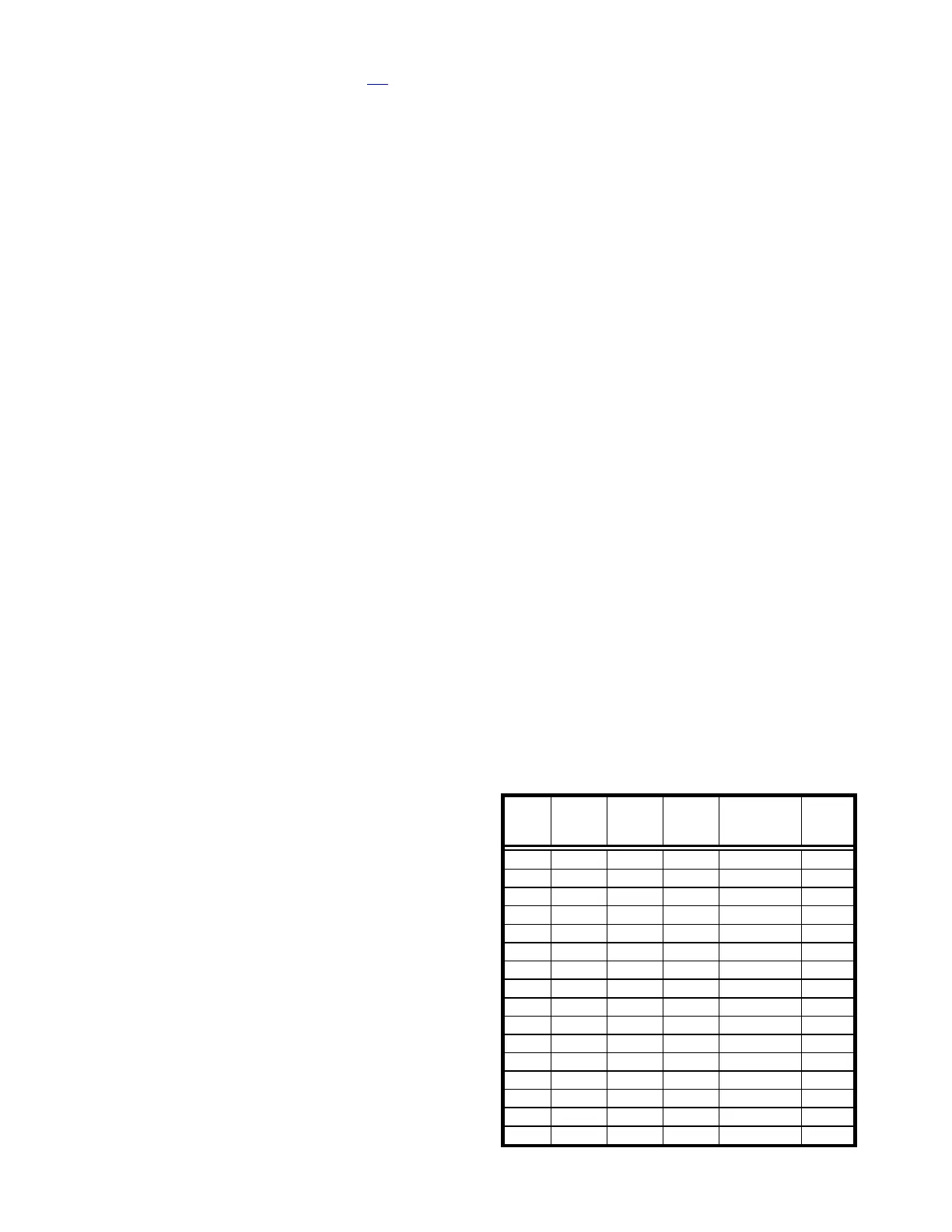
12. Straight-Line Move Speeds: Actual speed for the “Straight-
Line Move ‘S’“ command can be determined with the
following formula: (1300 / 16) * (sp +1), where 1300 is the
maximum speed in microns/second and “sp” is the speed level
0 (slowest) through 15 (fastest). For mm/second or
microns/millisecond, multiply result by 0.001.
Table E-10. Straight-line move ‘S’ command speeds.