MPC-385 SERIES OPERATION MANUAL – REV. 3.21K (20201120)
Command Sequence Formatting: Each command
sequence consists of at least one byte, the first of
which is the “command byte”. Those commands that
have parameters or arguments require a sequence of
bytes that follow the command byte. No delimiters
are used between command sequence arguments,
and command sequence terminators are not used.
Although most command bytes can be expressed as
ASCII displayable/printable characters, the rest of a
command sequence must generally be expressed as a
sequence of unsigned byte values (0-255 decimal; 00
– FF hexadecimal, or 00000000 – 11111111 binary).
Each byte in a command sequence transmitted to the
controller must contain an unsigned binary value.
Attempting to code command sequences as “strings”
is not advisable. Any command data returned by the
controller should be initially treated as a sequence of
unsigned byte values upon reception. Groups of
contiguous bytes can later be combined to form
larger values, as appropriate (e.g., 2 bytes into 16-bit
“word”, or 4 bytes into a 32-bit “long” or “double
word”). For the MPC-200, all axis position values
(number of microsteps) are stored as “unsigned
long” 32-bit positive-only values, and each is
transmitted and received to and from the controller
as four contiguous bytes.
Axis Position Command Parameters: All axis
positional information is exchanged between the
controller and the host computer in terms of
microsteps. Conversion between microsteps and
microns (micrometers) is the responsibility of the
software running on the host computer (see
Microns/microsteps conversion
table for conversion
factors).
Microsteps are stored as positive 32-bit values
(“long” (or optionally, “signed long”), or “unsigned
long” for C/C++; “I32” or “U32” for LabVIEW).
“Unsigned” means the value is always positive;
negative values are not allowed. The positive-only
values can also be stored in signed type variables, in
which case care must be taken to ensure that only
positive values are exchanged with the controller.
The 32-bit value consists of four contiguous bytes,
with a byte/bit-ordering format of Little Endian
(“Intel”) (most significant byte (MSB) in the first
byte and least significant (LSB) in the last byte). If
the platform on which your application is running is
Little Endian, then no byte order reversal of axis
position values is necessary. Examples of platforms
using Little Endian formatting include any system
using an Intel/AMD processor (including Microsoft
Windows and Apple Mac OS X).
If the platform on which your application is running
is Big Endian (e.g., Motorola PowerPC CPU), then
these 32-bit position values must have their bytes
reverse-ordered after receiving from, or before
sending to, the controller. Examples of Big-Endian
platforms include many non-Intel-based systems,
LabVIEW (regardless of operating system & CPU),
and Java (programming language/environment).
MATLAB and Python (script programming
language) are examples of environments that adapt
to the system on which each is running, so Little-
Endian enforcement may be needed if running on a
Big-Endian system. Some processors (e.g., ARM) can
be configured for specific endianess.
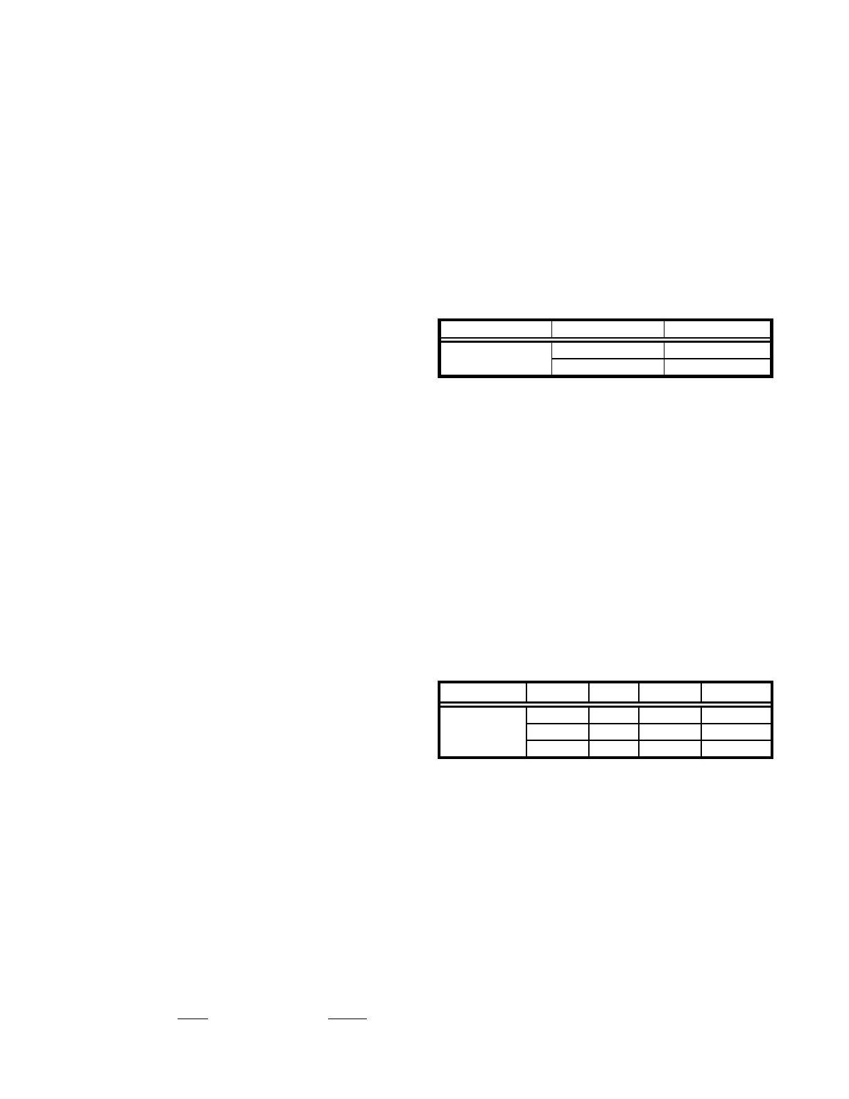
Microsteps and Microns (Micrometers): All
coordinates sent to and received from the controller
are in microsteps. To convert between microsteps
and microns (micrometers), use the following
conversion factors (multipliers):
Table E-6. Microns/microsteps conversion factors (multipliers).
micromanipulator
* Same applies to MP-225/M & MP-265/M micromanipulators,
3DMS/M & MPC-x8-series stages, and MOM & SOM microscope
objective movers. Other devices:
1.
MP-x45[S]/M series micromanipulator
(µstepsµm 0.046875; µmµsteps 21.333333333);
2.
MT-8x0 (MT-22xx) series translator
(µstepsµm 0.078125; µmµsteps 12.8 µsteps)
For accuracy in your application, type these
conversion factors as “double” (avoid using the
“float” type as it lacks precision with large values).
When converting to microsteps, type the result as a
32-bit “unsigned long” (C/C++), “uint32”
(MATLAB), or “U32” (LabVIEW) integer (positive
only) value. When converting to microns, type the
result as a “double” (C/C++, MATLAB) or “DBL”
(LabVIEW) 64-bit double-precision floating-point
value.
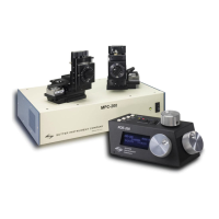
Table E-7. Ranges and bounds.
* Same applies to MP-225/M & MP-x45[S]/M-series
micromanipulators, 3DMS/M series stages, and SOM objective
mover.
Other devices:
•
TRIO MP-x45/M series micromanipulator and MPC-x8 series
stages: 25mm (533,333 microsteps) for X, Y, & Z. (Requires
firmware v3.19+.)
•
TRIO MP-865/M micromanipulator: 50mm for X, 12.5mm for
Y, and 25mm for Z. (Requires firmware v3.21+.)
•
MP-265/M micromanipulator: 25mm for X & Z, 12.5mm for
Y. (Discontinued product – replaced by TRIO MP-865/M.)
•
MT-8x0 (MT-22xx) series translator: 22mm in all three axes.
Only X & Y are connected to a motor (Z can be optionally
connected to a motor of another device (e.g., a focus drive)).
•
MOM objective mover (firmware v3.13 or 3.16, and device
Port A only): 21.5mm in all three axes.
Travel Speed: The following table shows the travel
speeds for single-, double-, and triple-axis