MPC-385 SERIES OPERATION MANUAL – REV. 3.21K (20201120)
4. OPERATIONS
4.1 First Time Use
4.1.1 Line Power (Mains)
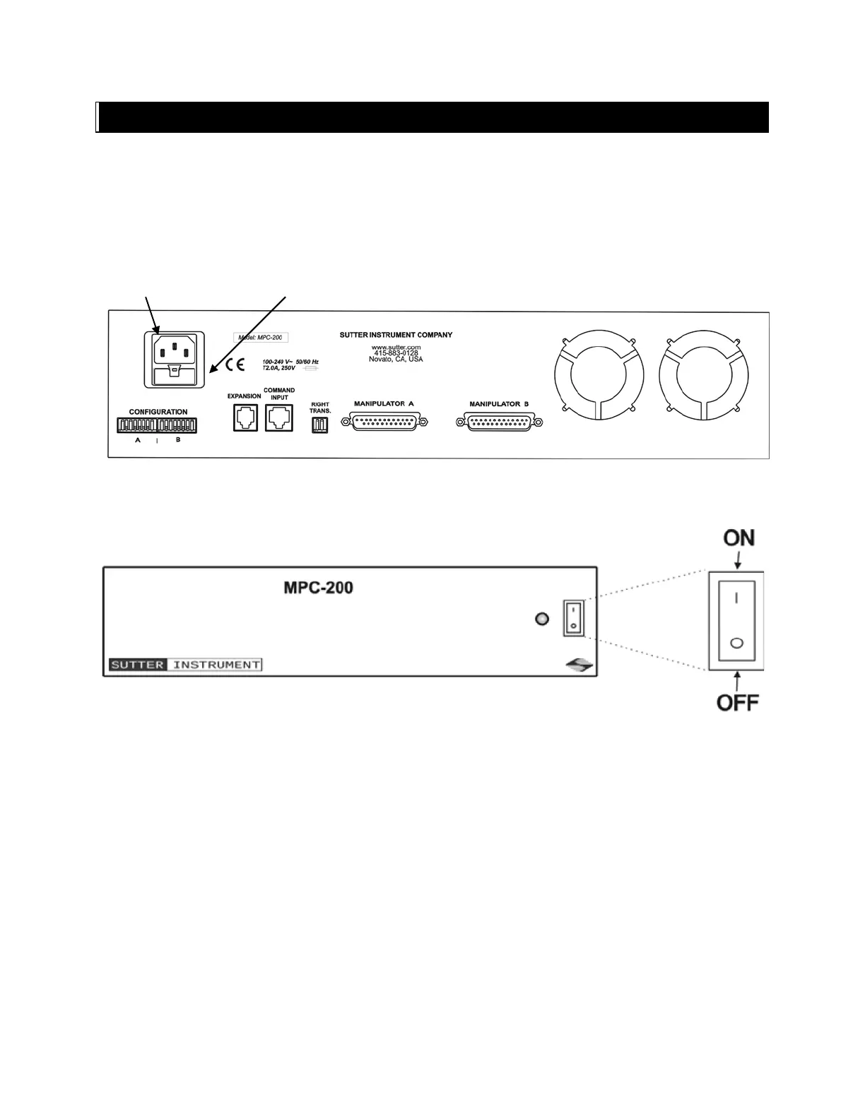
The power cord provided with the MPC-200 connects to the Power Entry Module located on
the back of the unit (see diagram below). This module also includes the line fuse .
Figure 4-1. MPC-200 Controller cabinet (rear view) showing power connection and fuse.
The power switch is located on the front panel as shown in Figure 4-2.
Figure 4-2. Power switch (front panel).
The MPC-200 has a “universal” power supply that runs on 110 volts or 220 volts AC, 50 or
60 Hz. You do not need to change settings or fuses to suit local conditions. Make certain that
the ON/OFF Switch located on the front panel of the MPC-200 cabinet is turned OFF. Plug
the power cord provided with the MPC-200 into the Line Input socket on the Power Entry
Module and then to a power source of the appropriate voltage and frequency.
You must replace the fuse with the appropriate value (see the Technical Specifications),
otherwise your protection from fire and electric shock will be compromised.
4.2 Make It Go
Turn on the power using the ON/OFF switch on the front panel of the MPC-200 controller
cabinet.