18
MPC-385 SERIES OPERATION MANUAL – REV. 3.21K (20201120)
not be correctly initialized. In this case, it is necessary to cycle the power off and on and run
CENTER again to its completion.
DIP Switches (on back of ROE-200): There are four DIP switches on the back of the ROE-
200 which govern global and/or ROE settings.
Switch 1: When ON, all modes on the MODE selector, except Mode 0 and 5, are
disabled. Some users may find that they only need Accelerated Mode and a single fine
mode. This will allow them to more easily switch between the two. Factory default is
OFF, enabling all modes.
Switch 2: When OFF, relative coordinates during Diagonal Mode are disabled. The
factory default is ON (display of relative coordinates enabled during Diagonal Mode).
Switch 3: When OFF, the MANIPULATOR Selector functions in a cyclical fashion.
After reaching the highest-numerated manipulator, a further push of
MANIPULATOR cycles the user back to the lowest-numerated manipulator. When
DIP switch 3 is set to ON, the selector does not cycle back to the first manipulator.
Factory default is OFF, allowing cycling back.
Switch 4: Reserved for future use. NOTE: Must be kept ON for proper functioning!
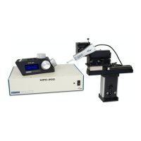
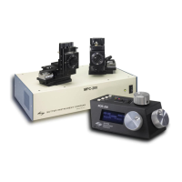
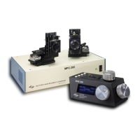
2.4 Controls on the MPC-200
Power Switch: The power switch for the MPC-200 is located on the front panel of the
controller. At power up, the microprocessor in the ROE-200 scans the attached equipment
and configures the system accordingly. Among the checks/configurations that are made:
1. Determines the number and type of manipulators that are attached. The MPC-200/ROE-
200 system is able determine how many and what type of manipulators (MP-285/M, MP-
225/M, or MP-265/M) are connected and to what outputs they are connected. It then sets
the current for each output to the correct value for the mechanicals found. If no
manipulators are found, the controller will return the message "NO MANIPULATOR
DETECTED, PLEASE TURN OFF CONTROLLER AND ATTACH MANIPULATOR"
2. The ROE-200 can connect to more than one MPC-200 controller. On power up, the ROE
determines how many controllers are attached and configures properly. If the power is off
on the second controller, the ROE-200 displays a message "PLEASE TURN ON ALL
CONTROLLERS, THEN PRESS SET TO START".
DIP Switches: Two banks of 8 DIP switches are located on the back of the MPC-200
controller. Each bank is assigned to, and configures, one of the two manipulator outputs on
the back of the controller (MANIPULATOR A or B). Users familiar with the Sutter
Instrument MP-225 controller will find that they have the same function as the configuration
DIP switches on the MP-225 ROE. The switches are numbered 1 through 8. In all cases, the 0
or OFF position is opposite the direction of the switch number and the 1 or ON position is in
the direction of the switch number and is also indicated by an arrow and the word “ON” next
to Switch 1. For any new switch settings to take effect, the controller must be powered off
and on.
The figure below shows the two banks of switches on the back of the MPC-200 controller.