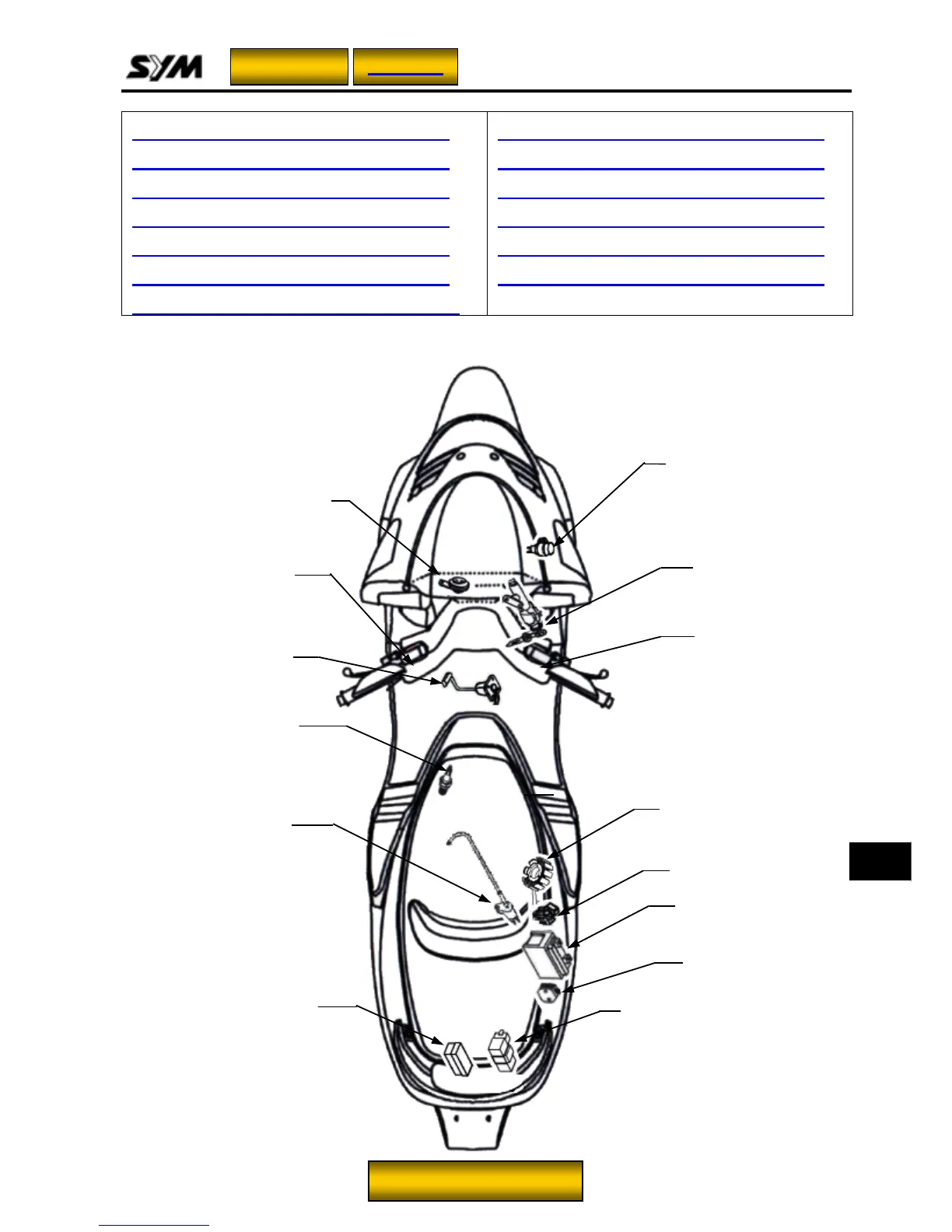
17. ELECTRICAL SYSTEM
17-1
Mechanical Illustration.................. 17-1
Maintenance Data.......................... 17-2
Trouble Diagnosis......................... 17-3
Battery............................................ 17-4
Charging System........................... 17-5
Ignition System.............................. 17-8
Starting System............................. 17-10
Lamp/Bulb ......................................17-12
Switch/Horn....................................17-13
Fuel Gauge .....................................17-16
Thermal Switch...............................17-17
Sensor.............................................17-18
Digital meters trouble diagnosis...17-19
Winker relay
Spark plug
AC.G.
High & Low beam /
Passing / Turn signal /
Horn switch
Fuses box
Battery
IGN. coil
Horn
Fuel unit
Ignition / Seat
open switch
C.D.I.
Regulator rectifier
Starter magnetic switch
Start / Light /
Engine stop switch
Homepage
Contents
17
To this chapter contents
 Loading...