17.ELECTRICAL SYSTEM
17-10
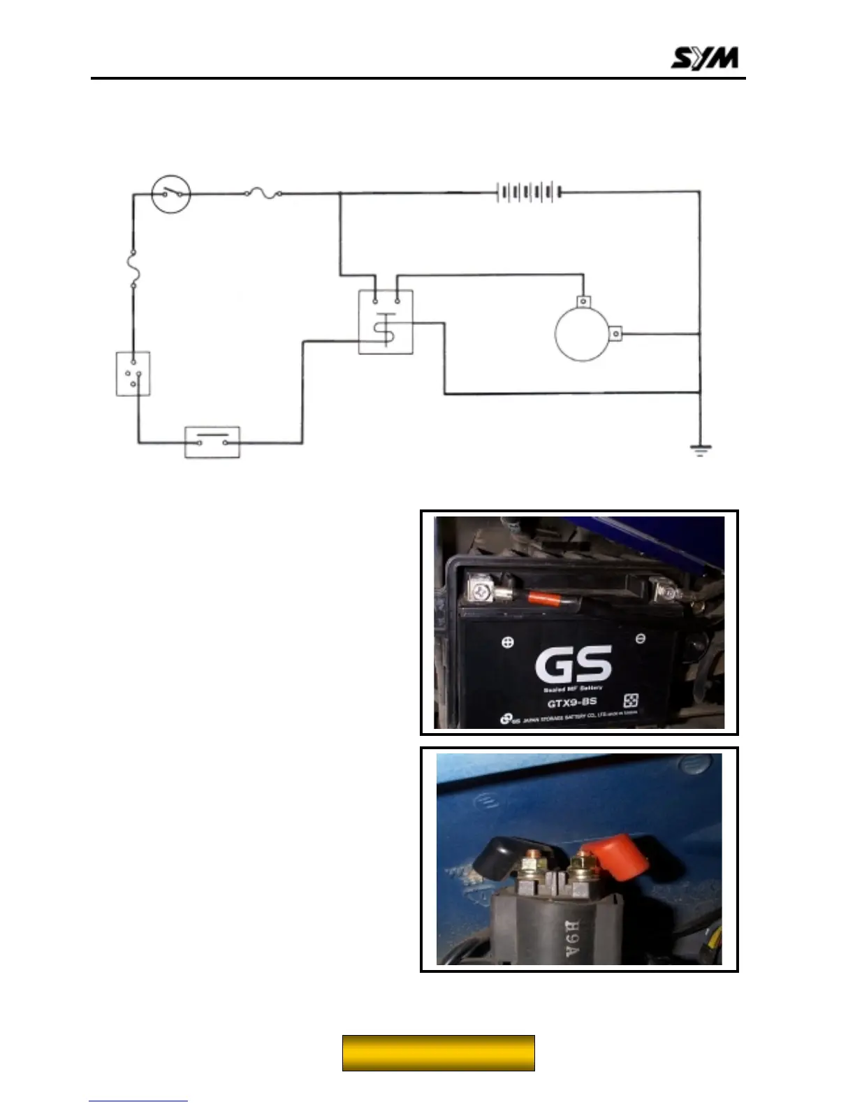
Starting System
Starting Circuit Diagram
Inspection on Starter Relay
Remove the luggage box assembly.
Open the main switch
Press the brake
Push down the starter switch
If a sound of “Looh Looh” is heard, it indicates
the relay function normally.
Disconnect the cable positive terminal from the
relay.
Disconnect the positive cable of the starter
motor.
Disconnect the connector of the relay.
Connect an ohmmeter to the large terminal end.
Connect the yellow/red cable to the battery
positive terminal and the green/yellow cable to
the battery negative terminal.
Check the continuity of the large terminal end.
If there is no continuity, replace the relay.
Main fuse 20A
Main switch
Main fuse 10A
Rear brake
switch
Starter switch
Starter relay
Starter motor
Red
Yellow/red
Green/yellow
To this chapter contents
 Loading...