Issue 3: Mar 96 TMSL 097-45018-02
Page 13
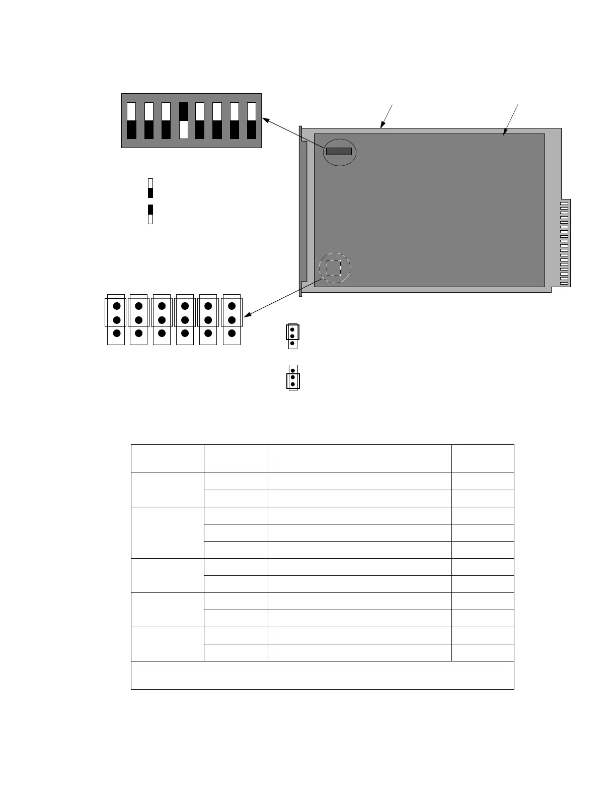
Figure 2. MIS Card Switch
J4 J5 J6 J7 J8 J9
SET ALL JUMPERS TO
SET ALL JUMPERS TO
DAUGHTER BOARD
MOTHER BOARD
LOCATED ON THE MOTHER BOARD
Note:
All switches are shown
in the factory-set position.
SW1
ON
81
LOCATED ON THE DAUGHTER BOARD
INDICATES OFF
INDICATES ON
THIS POSITION FOR
COM2 RS-232 PORT
THIS POSITION FOR
LOCAL COMM
SW1 Switch Settings
SW1 Section Position Description
Factory
Setting
1
On 1200 Baud —
Off 9600 Baud X
2 and 3
2=on, 3=any Odd Parity —
2=off, 3=on Even Parity —
2=off, 3=off No Parity X
4
On Password Protection Not Enabled X
Off Password Protection Enabled —
7
On Expansion Shelf —
Off Master Shelf X
8
On Remote System —
Off Not a Remote System X
Note: Section 1 sets COM2 and the front panel RJ45 jack only (active port selected by
jumpers).
Note: When setting jumpers, if
set for local comm, all ports will
be local only; if set for RS-232,
all ports will be RS-232 only.
 Loading...
