100 Reciter Disassembly and Reassembly TB8100 Service Manual
© Tait Electronics Limited September 2006
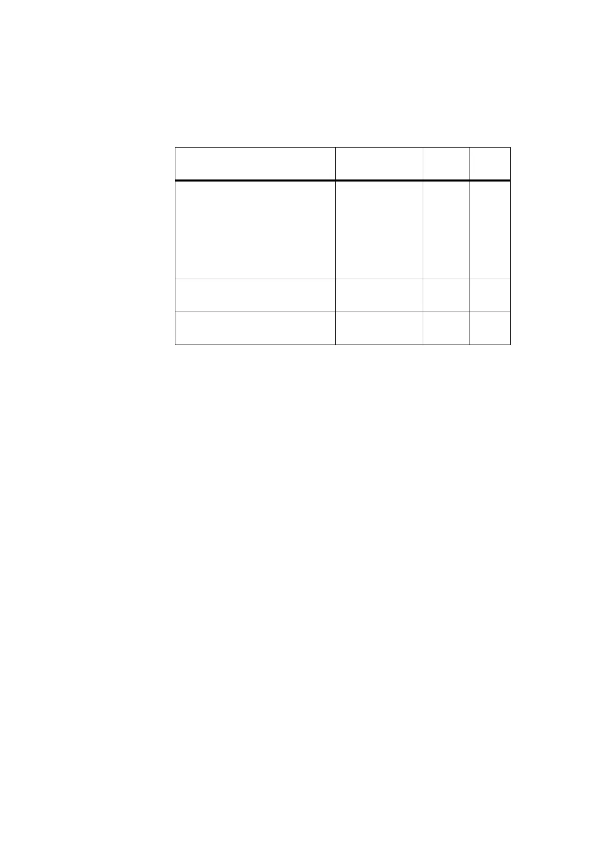
4.1 Screw Torque Settings
The recommended torque settings for the screws and nuts used in the reciter
are as follows:
4.2 Removing the Covers
1. Remove the M3 Torx screws securing the covers to the heatsink, and
to the front and rear panels. Lift off the covers.
4.3 Removing the Front and Rear Panels
The circled numbers in the following instructions refer to Figure 4.1.
1. Remove the four M2.5 Torx screws
b securing the SMA connector
to the heatsink and to the front panel.
2. Desolder the centre pin of the SMA connector
c from the RF board
and remove the connector.
3. Remove the two M3 Torx screws
d securing the handle to the
heatsink.
4. Remove the M3 screw
e securing the front panel to the heatsink,
and remove the front panel.
5. If necessary, remove the two M3 screws securing the fan duct
f to
the heatsink.
6. Remove the vent guard clip
g from the rear panel.
Location / Function Torque
Driver/
Spanner
Size
■ securing the side covers to the
heatsink and front and rear panels
■ securing the front and rear panels to
the heatsink
■ securing the handle to the front
panel
■ securing the boards to the heatsink
0.5N·m / 4.5lbf·in T10 M3
securing the SMA connector to the
front panel
0.3N·m / 2.5lbf·in T8 M2.5
securing the BNC/TNC connectors to
the rear panel
1.7N·m / 15lbf·in 11mm AF

 Loading...


