TB8100 Service Manual Reciter Circuit Description 27
© Tait Electronics Limited September 2006
2 Reciter Circuit Description
This chapter describes the circuitry used in VHF and UHF reciters. Much
of this circuitry is common to both frequency bands, and is therefore
covered by a single description in this chapter. Where the circuitry differs
between VHF and UHF, separate descriptions are provided for each
frequency band. In some cases the descriptions refer to specific VHF or
UHF bands or sub-bands, and these are identified with the letters listed in
the following table (refer to “Identifying the Reciter” on page 70 for more
details).
The reciter comprises three boards: an RF board, a digital board, and an
optional system interface board. These boards are mounted on a central
chassis/heatsink. Figure 2.1 on page 28 shows the configuration of the main
circuit blocks, and the main inputs and outputs for power, RF and control
signals. The locations of the main circuit blocks on the boards are shown in
Figure 2.14 on page 61, Figure 2.15 on page 63, Figure 2.16 on page 65,
and Figure 2.17 on page 67.
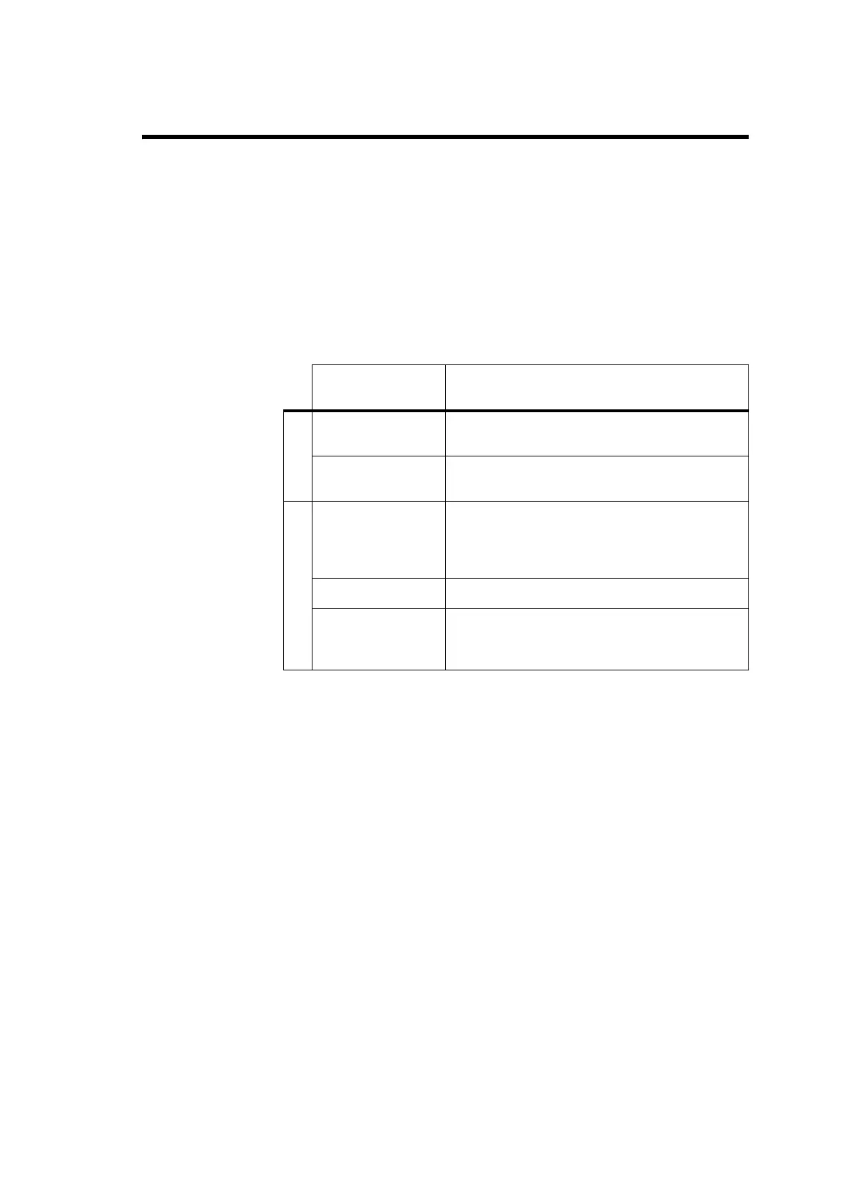
Frequency
Identification Frequency Band and Sub-band
VHF
B band B2 = 136MHz to 156MHz
B3 = 148MHz to 174MHz
C band C1 = 174MHz to 193MHz
C2 = 193MHz to 225MHz
UHF
H band H1 = 400MHz to 440MHz
H2 = 440MHz to 480MHz
H3 = 470MHz to 520MHz
H4 = 380MHz to 420MHz
K band K4 = 762MHz to 870MHz
a
a. The actual frequency coverage in this band is:
Transmit: 762MHz to 776MHz, and 850MHz to 870MHz
Receive: 792MHz to 824MHz
L Band L1 = 852MHz to 854MHz, and 928MHz to 930MHz
L2 = 896MHz to 902MHz (receive only)
L2 = 927MHz to 941MHz (transmit only)

 Loading...


