208 Power Management Unit Circuit Description TB8100 Service Manual
© Tait Electronics Limited September 2006
System Interface
and Fan Control
The system interface circuitry consists of the I
2
C lines, fan power, and alarm
outputs, which are fed to the system control bus connector on the front
panel. There is high frequency filtering on all lines.
The microprocessor also monitors the current drawn by the PMU fan and
protects it from overload or short circuit.
Interface to DC
Module
This interface consists of the connectors which connect the AC module to
the DC module. Although there is no circuitry involved this interface, it is
included in the block diagram to illustrate the interconnection between the
AC and DC modules.
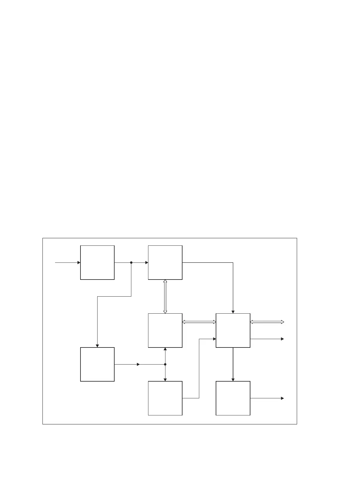
12.3 DC Module
The DC module accepts an input of 12VDC, 24VDC or 48VDC nominal,
and provides two regulated 28VDC outputs: high current for the PA, and
low current for the reciter.
The main circuit blocks are shown in Figure 12.4 below, and are described
in more detail in the paragraphs which follow.
Figure 12.4 PMU DC module block diagram
EMC Filter
and
Protection
DC Power
Converter
(DCDC)
DC Control
Battery
Control
Standby
Power
Supply
Auxiliary
Power
Supply*
Interface to
AC Module
DC I/P
12/24/48V
Control &
Monitor
DC
*optional
DC O/P
13.65/27.3/54.6V

 Loading...


