180 Power Amplifier Board Replacement TB8100 Service Manual
© Tait Electronics Limited September 2006
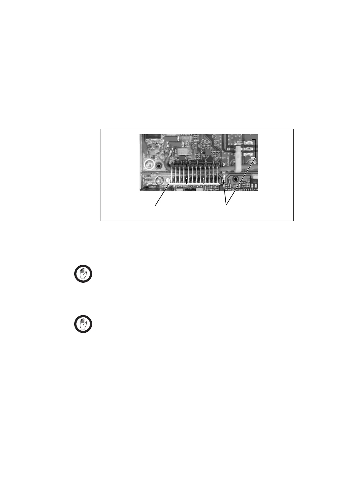
10.1 Circuit Board Connecting Links
There are two types of link used to connect individual boards in the PA:
■ RF links b are used to carry RF signals from one board to another
■ bridging links c are used to carry control signals from one board to
another.
Figure 10.1 shows typical examples of both types of links.
10.2 Replacing the 6W Board
Important There is heatsink compound between the board and the
heatsink under certain components. Any objects caught in
the heatsink compound underneath the board which pre-
vent effective heatsinking may cause these components to
fail.
Important If you replace the 6W board, you must recalibrate the PA
bias using the Calibration Kit. Refer to the Calibration Kit
documentation for more details.
Refer to “Power Amplifier Disassembly and Reassembly” on page 173 for
details on removing and refitting the cover and front panel, and for screw
torque settings. The circled numbers in the following instructions refer to
Figure 10.2 on page 181. Figure 10.2 shows a 50W UHF (H-band) PA.
The exact number and location of links may differ in other models.
Removal 1. Remove the cover and front panel.
2. Remove the bridging links
b connecting the board to the control
board.
Figure 10.1 Circuit board connecting links
bc

 Loading...


