TB8100 Service Manual Power Management Unit Fault Finding 223
© Tait Electronics Limited September 2006
Task 1 —
Check Power-up
and Output
Voltages
1. Before starting any of these fault finding procedures, you must iden-
tify the model and hardware configuration of the PMU under test.
“Identifying the PMU” on page 217 explains how to identify a PMU
from the product code printed on a label on the rear panel.
2. Set up the test equipment as shown in Figure 13.2 on page 222. Do
not fit the front panel to the subrack.
3. Connect the PMU to the appropriate AC or DC power supply.
Switch the PMU on. The recommended DC input voltage for this
initial power-up is 16VDC (32VDC) [64VDC].
Note These voltages are above the upper limit of the
user-programmable startup voltage (refer to Table 13.4 on
page 239). This should ensure that the PMU powers up, even if
the startup voltage limit has been set to the maximum value.
4. Check whether the LEDs
b on the front panel are flashing (refer to
Figure 13.3). If they are, go to Task 2
. If they are not, go to Step 5.
5. Check the output voltage at either PA connector
c on the front
panel. If the PMU is fitted with an auxiliary power supply board, also
check the output voltage at the connector
d on the rear panel. The
voltages should be as listed in Table 13.1.
If the output voltages are correct, go to Task 3
. If the PA output volt-
age is wrong or not present, go to Step 6. If the auxiliary output volt-
age is wrong or not present, go to “Auxiliary Power Supply Board”
on page 229.
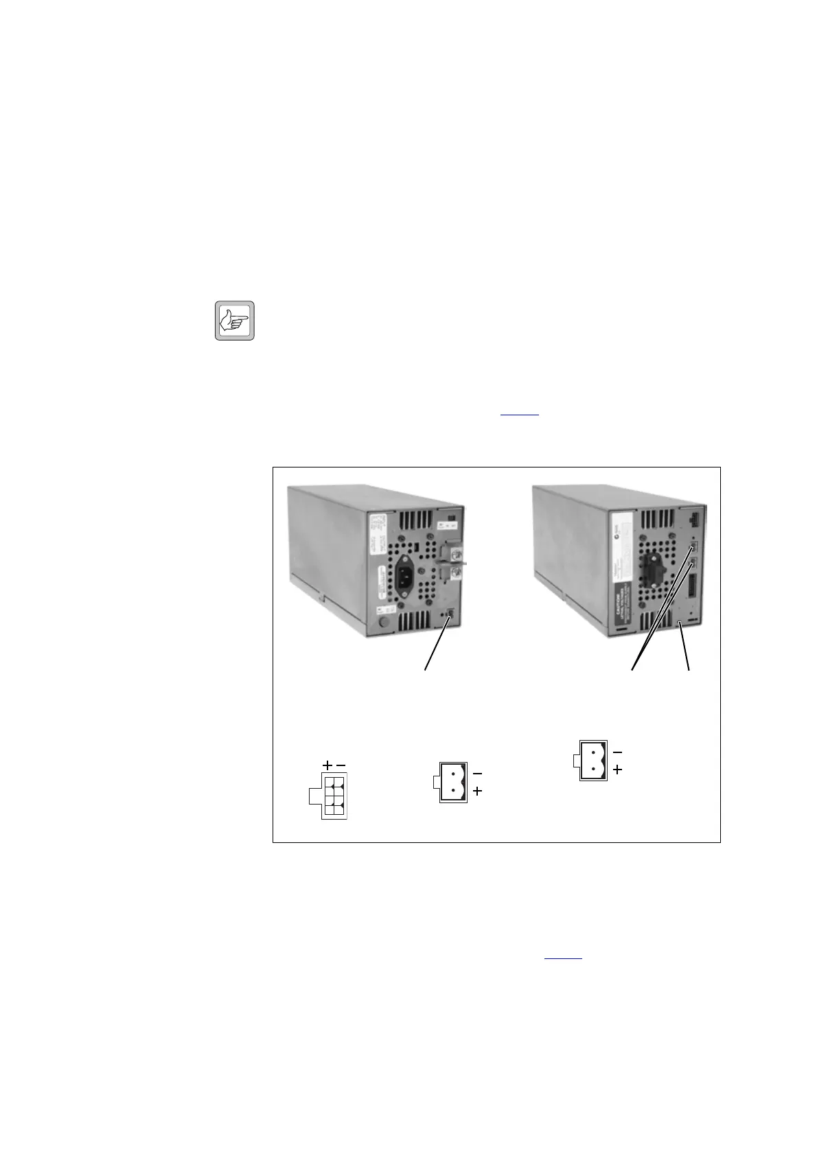
Figure 13.3 Location of indicator LEDs and DC output connectors
dc
rear view
b
front view
1
5
26
37
48
pins 1-4pins 5-8
auxiliary DC output connectors
original type later type
PA DC output connectors

 Loading...


