TB8100 Service Manual Power Management Unit Fault Finding 231
© Tait Electronics Limited September 2006
5. Measure the voltage at the DC output connector b shown in
Figure 13.5. The voltage should be 28.7VDC±10%.
Note The voltage measured may be different from the stated value
because it is not under control of the microprocessor, or because
of component tolerances.
If the voltage measured is within tolerance, go to Step 6. If the volt-
age is too low or too high, replace the DC control card and repeat this
task. If there is no voltage present, replace both the DC control card
and battery control card and repeat this task. If the voltage is still
incorrect after replacing the cards, go to Task 4
.
6. Connect a load to the DC output connector. This will test the
regulation to see if the output remains constant under load. If the
output voltage remains steady, go to Task 2
. If it does not, replace the
DC control card and repeat this step. If the voltage does not remain
steady after replacing the card, go to Task 4
.
Note The DC input supply must be rated for the load you connect to
the output of the DC converter, otherwise the input supply will
current limit.
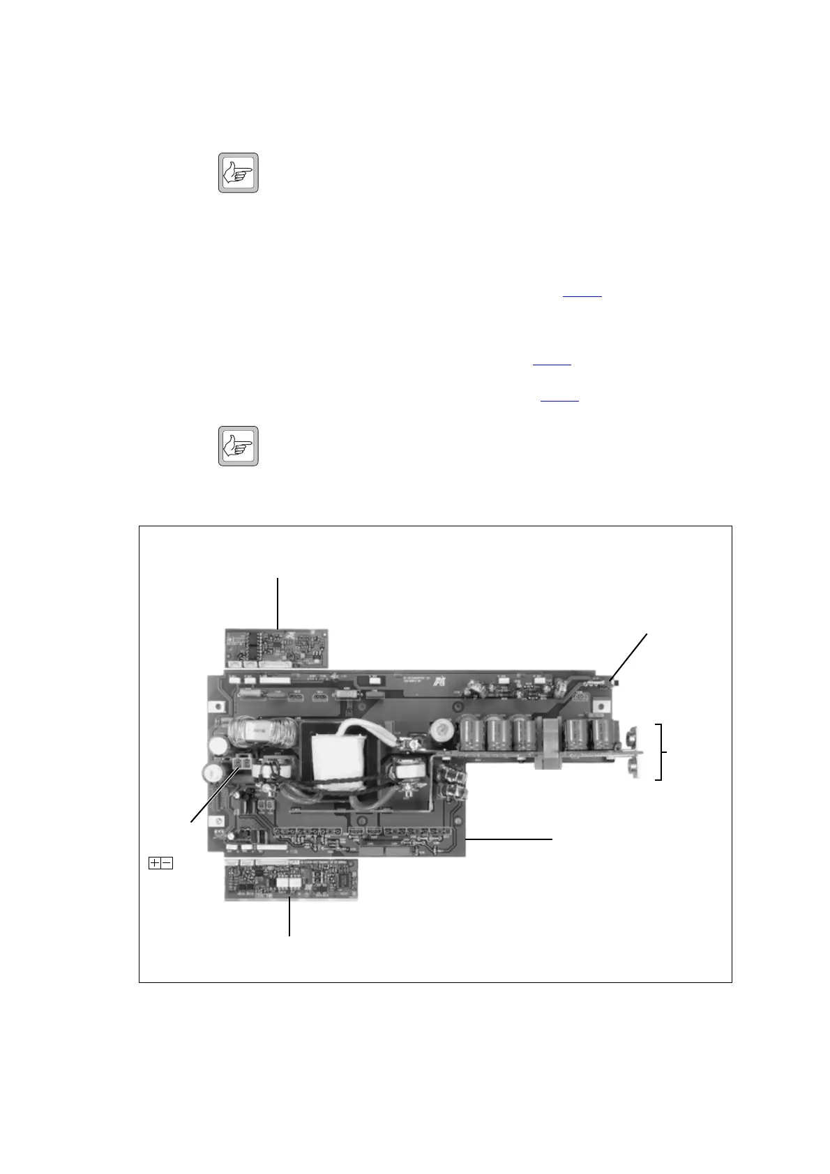
Figure 13.5 Checking the DC converter without microprocessor control
battery control card
DC control card
DC converter board
DC input
DC output
+
–
DC on/off switch
on = up
off = down
Note:
In order to show as much of the circuitry as possible
in the photograph, the heatsinks and the
components normally attached to them are not
fitted, and the plug-in cards are not plugged in.
b

 Loading...


