TB8100 Service Manual Power Management Unit Spare Parts 269
© Tait Electronics Limited September 2006
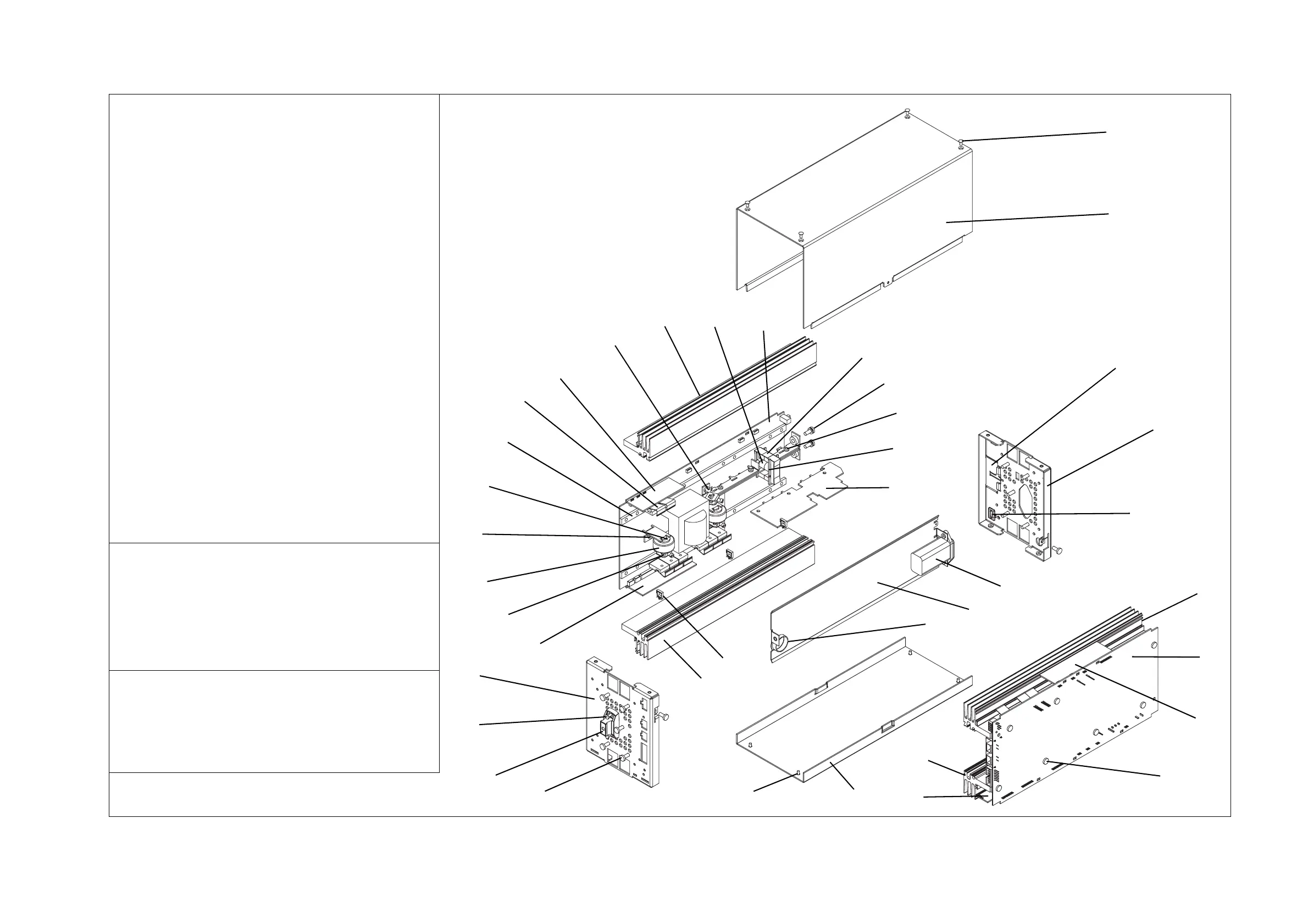
Figure 16.1 PMU mechanical assembly - sheet 1
Description IPN
b current transformer 053-00028-XX
c E-core choke 069-00010-40
d clamp for E-core choke 069-00010-41
e AC mains input connector 219-02843-XX
f E-core choke PCB 220-02023-XX
g 4mm bus bar terminal 240-04030-44
h retaining clip (holds device against heatsink) 303-50040-XX
i handle 308-01065-XX
j heatsink 308-13146-XX
1) heatsink insulator 309-01051-XX
1! DC input insulator 309-01052-XX
1@ bottom cover 316-06811-XX
1# front panel 316-06812-XX
1$ rear panel 316-06813-XX
1% top cover 316-06814-XX
1^ shield 319-01246-XX
1& M6x12mm pan head Pozidriv screw 345-00070-05
1* M3x6mm countersunk Torx screw 345-40460-XX
1( M3x8mm pan head Torx Taptite screw 349-00020-36
2) M4x12mm pan head Torx Taptite screw 349-02058-XX
2! M3x10mm pan head Torx Taptite screw 349-02066-XX
2@ wire retaining clip (if 40W aux. PS board fitted) 357-01051-XX
2# plastic grommet 360-02026-XX
2$ M3 T03 insulator bush 362-00010-11
2% 10mm ID insulator bush with shoulder 362-00011-XX
2^ seal (when 40W aux. PS board not fitted) 362-01122-XX
2&
AC converter board
2* PFC control card
2( HVDC control and microprocessor card
3) DC converter board
3! DC input filter card
3@ DC control card
3# battery control card
Not Shown in this Drawing
12-way ribbon cable between AC and DC modules 219-02629-XX
8-way cable for auxiliary power supply board 219-02844-XX
28VDC cable between AC and DC modules 219-02846-XX
thermally conductive insulator sheet 16x22mm 362-01116-XX
thermally conductive insulator sheet 130x22mm 362-01117-XX
Note:
The characters XX in an IPN (Tait Internal Part Number)
stand for the issue number of the part. Only the latest
issue of each part will normally be available for ordering
as spare or replacement parts.
Note:
This drawing shows an AC and DC PMU. Those parts
fitted only to an AC PMU or a DC PMU are shown in
sheet 2.
1*
1%
1!
1$
2^
j
2&
2*
2)
2(
j
1@
1*
2#
1^
e
2)
i
2!
1#
2@
j
b
2)
2%
1)
h
3#
2)
jc
3)
d
1&
1(
f
3!
3@
2$
x4
x7 each
module
x4
x5 each end
x3
x2
g
x3
x2
x2 per
transformer
x1 per
heatsink
x2
x2
x3
x2
x2

 Loading...


