TP9100 Service Manual Description 47
© Tait Electronics Limited May 2005
Power Control
The power control uses the power-sensing method. The steady-state power
output of the transmitter is regulated using a hardware control loop. The DC
current drawn by the PA is sensed via a 0.1Ω resistor, and the minute voltage
difference is amplified by a difference amplifier. The amplified difference
voltage is compared by the integrator with the set reference voltage available
from the CODEC. The PA output power is controlled by varying the driver
gate bias voltage and—for the UHF band—the base of the pre-driver stage.
The driver gate voltage is hardware-limited to prevent overdrive.
The reference voltage for the loop is supplied by a 13-bit DAC. The system
driving the DAC supplies the steady-state voltage for a given power level as
determined by factory calibration. The bandwidth of the loop is high to
ensure that the loop does not limit the ramping slope and has approx. 25dB
power control range. Under load mismatch at the antenna (predetermined
VSWR), the current drawn by the PA is maintained relatively constant and
the output power is allowed to vary within predetermined limits.
Ramping Power ramp-up consists of two stages:
■ bias
■ power ramping
The timing between these two stages is critical to achieving the correct
overall wave shape in order to meet the specification for transient ACP
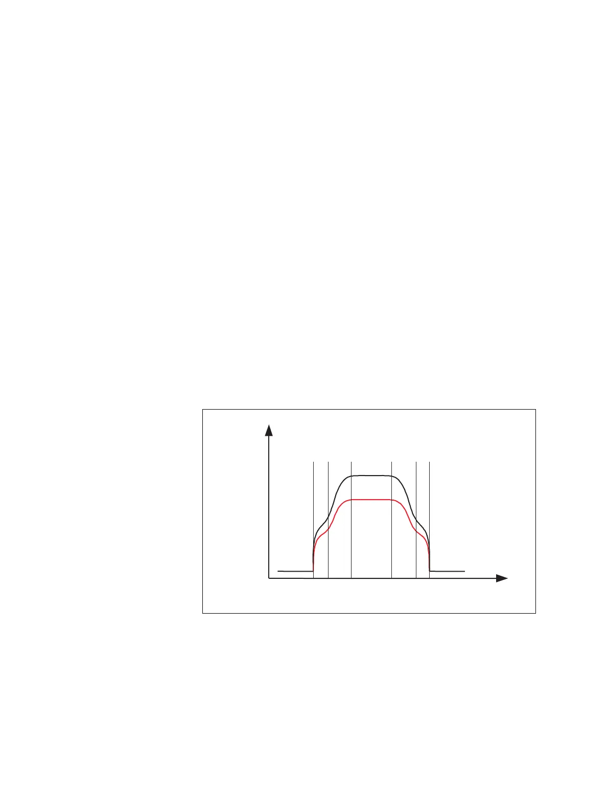
(adjacent channel power). A typical ramping waveform is shown in
Figure 2.8.
Figure 2.8 Typical ramping waveforms
Power
ramp
High power
powerLow
Power
Time
Bias
ramp
Bias
ramp
Power
ramp