Drive Axle
Page 38
E-451 & E-457
ME-45X-01
PRIMARY REDUCTION CASE
This section is one section of a complete service
manual. Before starting any procedure, read all
warnings and instructions that are located in the
Service Guidelines chapter.
WARNING
Note: Some vehicle congurations may require
that the transmission be removed to
disassemble the chain case.
Disassemble
1: Place an oil drain pan under the chain case.
2: Remove the chain case drain plug and allow all of
the oil to drain from the housing and then reinstall
the drain plug
3: Remove the brake drum. Refer to section
Brakes: Replace the Brake Drum for information
regarding removing the brake drum.
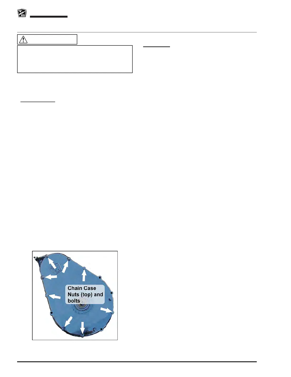
4: Remove the nuts from the three threaded studs
at the small end of the chain case housing.
5: Remove the chain case housing bolts, brake
assembly, and alignment brackets.
6: Remove the chain case housing from the backing
plate.
7: Remove the pinion seal from the chain case
housing.
8: Loosen the motor mounting bolts.
9: Loosen the chain adjuster.
10: Remove the drive chain, motor nut and sprocket
and the drive sprocket.
11: If the backing plate must be removed from the 3rd
member, rst remove the motor from the backing
plate then remove the backing plate from the 3rd
member.
Assemble
1: Thoroughly clean all gasket surfaces.
2: Apply a 1/8” bead of 94-430-03 gasket sealer to
the face of the 3rd member.
3: Install the backing plate to the 3rd member.
Tighten to torque specied in the Hardware
Torque table at the end of this section.
4: Install the motor to the backing plate. Do not fully
tighten the motor mounting hardware at this time.
5: Install the motor sprocket, drive sprocket and
chain. Do not adjust the chain tension at this time.
6: Apply a 1/8” bead of 94-430-03 gasket sealer to
the chain case housing.
7: Install the chain case centering tool (refer to
Appendix A) into the pinion seal bore in the chain
case housing.
8: Install the chain case housing onto the pinion
shaft and tighten the pinion nut to 75 foot pounds
(105 Nm).
9: Install and tighten the three nuts and washers
to the threaded studs and the housing bolts that
are not used for the brake mounting bracket or
alignment brackets.
10: Remove the centering tool and install a new
pinion seal. Lightly lubricate the pinion seal lip.
11: Install the brake assembly and the brake band
alignment bracket(s). Do not tighten the bolts at
this time.
12: Install the brake drum. Tighten to torque specied
in the Hardware Torque table at the end of this
section.
13: Temporarily tighten the brake adjusting bolt to 25
foot pounds (33 Nm).
14: Tighten the brake assembly mounting bolts.
15: Adjust the brake. Refer to Brake section for
information regarding adjusting the brakes.
16: Adjust the drive chain. Refer to section Adjust the
Drive Chain.