Brakes
Page 54
E-451 & E-457
ME-45X-01
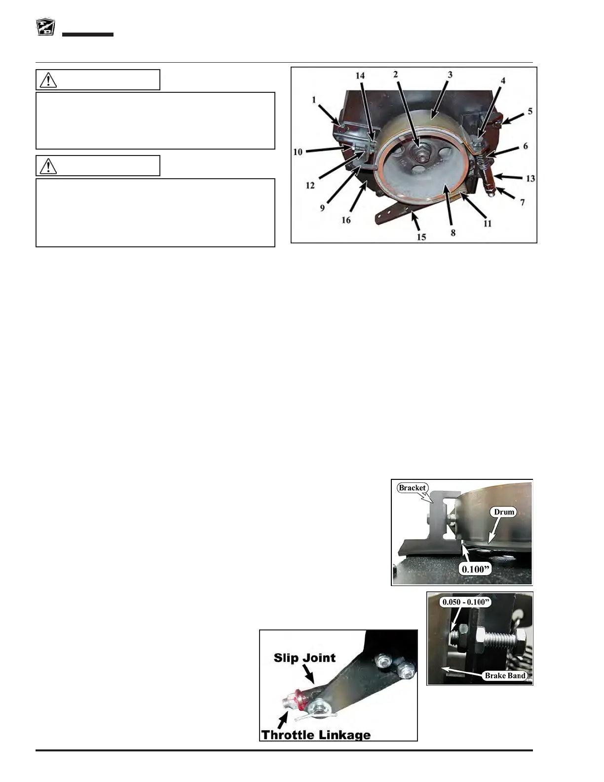
REPLACE BRAKE BAND
Note: Refer to the illustration for locations of the components.
Note: Onmostvehiclecongurations,thebrakedrumdoesnothavetoberemovedforthisprocedure.Ifthe
brake drum must be removed, refer to the Replace Brake Drum section.
1: Press the treadle to release the brake
2: Disconnect the brake linkage from the brake arm (15).
3: Loosen the bolt(s) (1) on the brake band alignment bracket(s) (9) and pivot them out of the way.
4: Remove the bolts (5) holding the brake band assembly to the front of the chain housing (16) and remove the
brake band assembly from the drive.
5: Remove the brake band bolt (4).
6: Remove the clevis pin (11) from the brake band anchor and remove the brake band (3) from the assembly.
7: Inspect the brake arm pivot bolt for signs of wear. If any signs of wear are seen then the pivot bolt must be
replaced.
8: Tighten the brake band pivot bolt and then back off just enough so that the brake arm (15) pivots freely.
9: Install the new brake band using new hardware.
10: Install the brake band assembly onto the drive. Tighten the mounting bolts (5) just enough to keep the
mounting bracket (13) against the chain case (16) but still allowing the bracket to move.
11: Tighten the brake band bolt (4) to 50 foot pounds (70 Nm).
12: Tighten the brake band bracket mounting bolts (5).
13: Position the brake band alignment bracket(s) (9) so that the inner arm (14)
is 0.100 inch (2.54 mm) away from the brake drum (8). Make certain that
the alignment bracket does not come into contact with the brake drum.
14: Adjust the alignment bracket adjusting bolt(s) (10) to 0.050-0.100 inch
(1.27- 2.54 mm) away from the brake band and tighten the jam nuts (12).
15: Connect the brake linkage to the brake arm and adjust the linkage so that
the brake arm is contacting the chain case when the treadle is fully pressed
(level with the oorboard).
16: Release the treadle and then press again until the stop nut on the throttle
linkage is in contact with the accelerator module slip joint and (see below).
17: Loosen the brake band adjusting bolt (4) and adjust so that there is a slight brake
drag. It may be necessary to readjust the alignment bracket adjusting bolt(s) (10)
for optimum brake alignment and operation.
18: Tighten the brake band bolt jam nut (7).
19: Test drive.
The brake band bolt, spring, lock nut, jam nut, clevis
pin, and cotter pin must be replaced with new parts
whenever the brake band is replaced. Failure to
replace these components could cause the parking
brake to fail resulting in severe bodily injury and/or
property damage.
WARNING
This section is one section of a complete service
manual. Before starting any procedure, read all
warnings and instructions that are located in the
Service Guidelines chapter.
WARNING
 Loading...