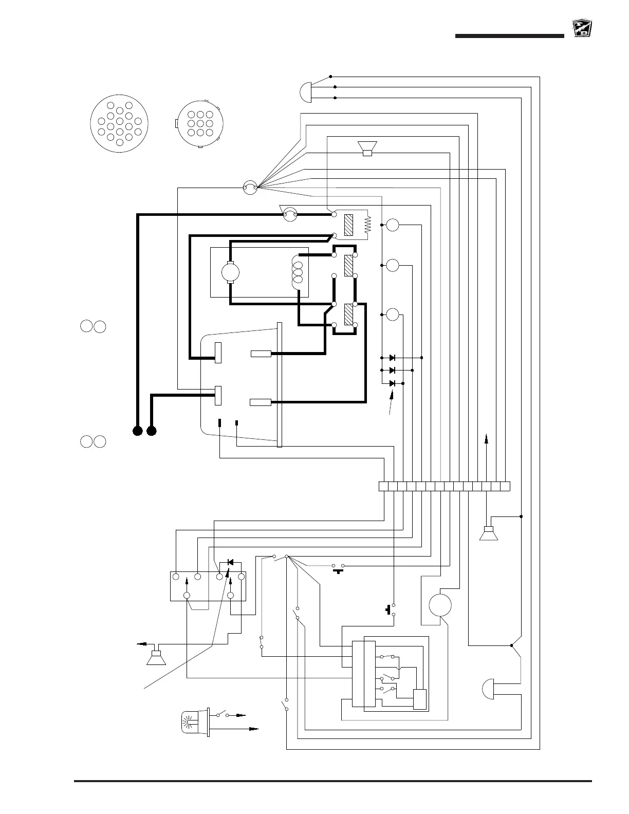
Wire Diagram
Page 71
E-451 & E-457
E-451 & E-457
SCH-00055, 12/16/2014, Revision C
Typical diagram shown. May not include special order options or accesories.
Typical Curtis PMC Control System (no 12v tap)
R1 = 250 Ohm 5 Watt ResistorCB = Circuit Breaker
Isolator solenoid or contactor coil
R
FI
Reverse solenoid or contactor coil
Forward solenoid or contactor coil
BSI
Battery Status Indicator
Note 1: The charger interlock is optional and
may not be installed on your vehicle. If
equipped with the charger interlock option the
interlock relay will be located in the main
charger cabinet or in a seperate module
external of the charger.
Optional Motion Alarm
Optional Strobe Light
To Black on BSI
To Hot or Cold
Side of Key Switch
Brown
Red
BSI
Head Light
A
MOTOR
S1S2
A2
BL
F R I
A1
Blue
Green
Yellow
Green
KSI
B- B+
A2
M-
White
CB
135A
Black
Red
Red
Forward/Reverse Switch
Blue/Black
White/Black
Orange/Black
Green/Black
Horn
#2
R1
Violet/Black
PMC CONTROL
8
10
5
6
1
2
7
4
9
White
Black
Red
14
10A
CB
Light Switch
Blue
Violet/Black
Harness Connector
Red
Brown
White
Green/Black
White/Black
Blue/Black
Orange/Black
Blue
Orange
Orange
Brake Light Switch
LIGHT
TAIL/STOP
F
R
Diodes used on
48-volt systems
only
Green/Black
Violet/Black
Violet/Black
Red
Brown
Blue/Black
White/Black
Green/Black
Red
Black
Blue
Red
White
Orange/Black
Black
White White
Brown
Orange
White
Brown
Orange
White
Black
Red
Red
Black
Black
White
Violet/Black
Orange/Black
Black
Black
White
Red
Brown
Orange
Main Battery Positive
Main Battery Negative
Black
Red
White
Green/Black
Violet/Black
Violet/Black
Horn
Switch
Charger
Interlock Relay
Contacts
Key
Switch
14
16
6
10
2
15
7
3
11
1
View from wire side
1
3
4
7
6
9
View from pin side
Harness Connector
Accelerator Module Connector
16
White
White
3
Connect to Forward or Reverse (+) for motion alarm
12
11
Black
Black
Black
White/Black
Black
ACCELERATOR
9
9
PCB
MS3
MS1
MS2
5
5
6
6
4
4
2
2
7
7
Black
Black
Yellow/Black
To B-
Optional Rev Alarm wiring
6-11v out>
Seat or Foot
Interlock