89
vP-2 sTErEO
Main
Operation
Pitch mode
Range:StereoLinkedorDual
StereoLinked
In this mode the parameters for left and right channels are
linkedandphase-lockedandchangesofanyparametervia
Faders1and2willbeperformedonbothchannels.
Dual
In Dual mode various parameters are available for both
left and right channel. As the processing is completely
independent for the two channels, this processing can be
conceived as a Dual Pitch Brain mode.
Input Levels
InLevel L/InLevel R
Range: -100dB to 0dB
Sets the Input level for left and right channel.
Output Levels
Wet Level L/ Wet Level R
Range: -100dB to 0dB
Sets the” Wet” Output level for left and right channel.
Dry Level L/ Dry Level R
Range: -100dB to 0dB
Setsthe“Dry”Outputlevelforleftandrightchannel.
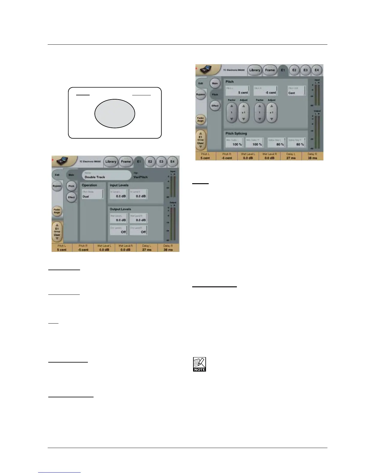
Pitch
Pitch
Pitch L/ Pitch R
Range:+/-1200centor+/-100%
Usethisparametertospecifythetransposevalue.
Pitch Unit
Chose whether the transpose amount should be displayed
in cent, % or semitones.
Factor/Adjust
Range: 1, 10 or 100
TheFactorparameterisamultiplierfactorfortheAdjust
handles.UsetheAdjusthandlestofine-tunethetranspose
value.
Pitch Splicing
The Splicing parameters are used to optimize how the pitch
brains compute the splice points. If very short Delay times
are used, audio quality trade-offs must be expected.
Max Delay - Left & Right
Range: 0 to 100%
Sets the maximum delay used for pitch change purposes.
If low processing Delay is important, this parameter should
be set at minimum value when listening for splicing artifacts
passing the lowest expected audio frequency.
TheDelayfoundintheEffectsectionaddstothe
Max Delay.
Splice Size
Range: 0 to 100%
Sets the maximum timing variation allowed when the pitch
brainlooksforperfectsplicepoints.
Ifsplicingintervalshavetobekeptconstant,thiscontrol
should be turned towards low values.
The VP-2 Stereo algorithm occupies :
@ Normal Sample Rate : 1/4 DSP Resource
@ Double Sample Rate : Not available
Algorithm Inputs/Outputs are distributed as follows:
E1 - E4
L
R
L
R
INPUT
OUTPUT
•
•
•
•
•
•
•
•
•
•
•
•
•
•
•
•
 Loading...