112
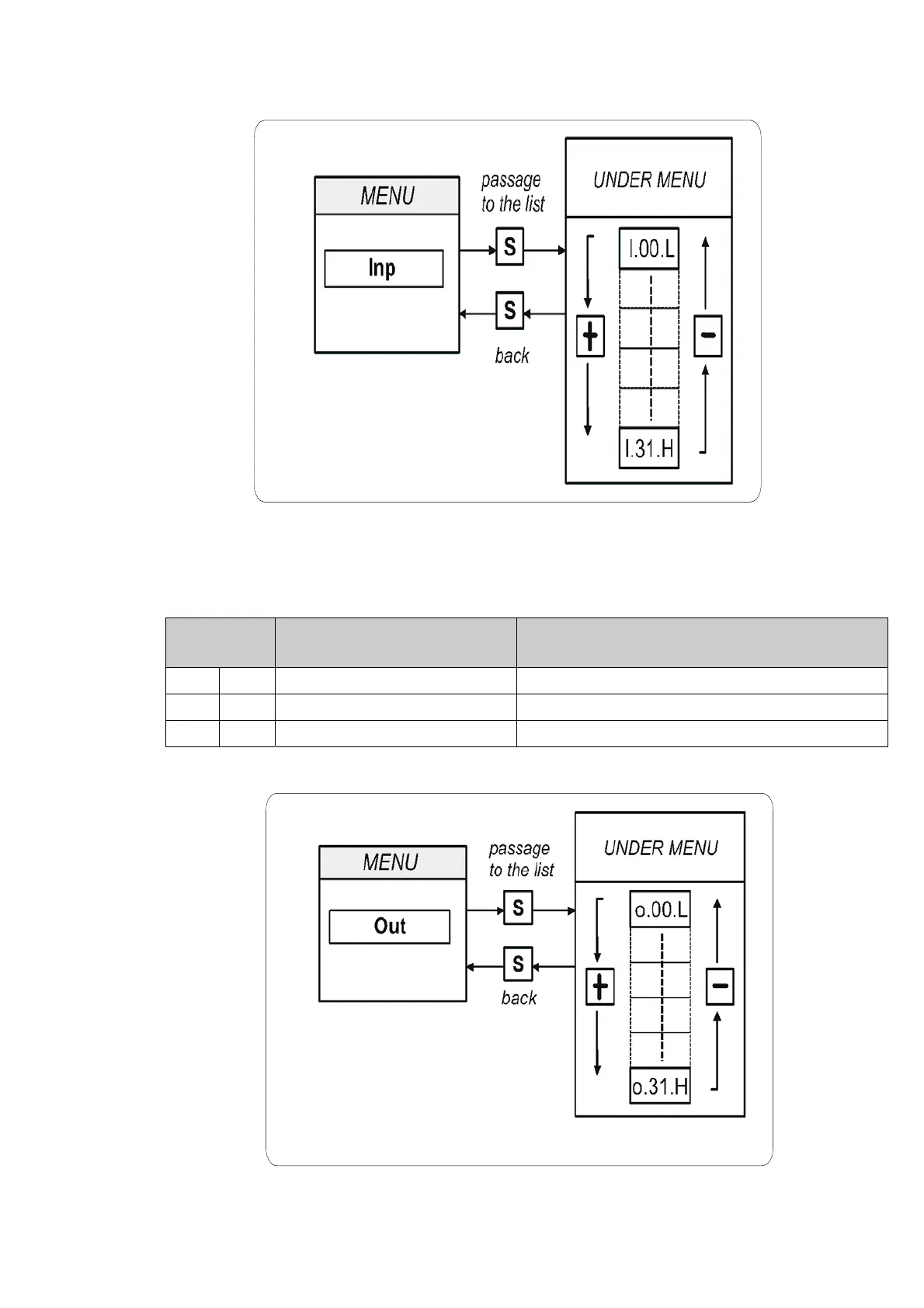
FIG. 15 (Digital input INP)
To note the last three digital input are about the power logical input:
FIG. 16 (Digital output OUT)
POWER LOGICAL INPUT STATUS (H= ON L= OFF)
I 29 / PTM H= OK; L= active alarm
I 30 / MAXV H= OK; L= active alarm
I 31 / MAINS SUPPLY OFF H= OK; L= active alarm