80
4.2 CAN OPEN
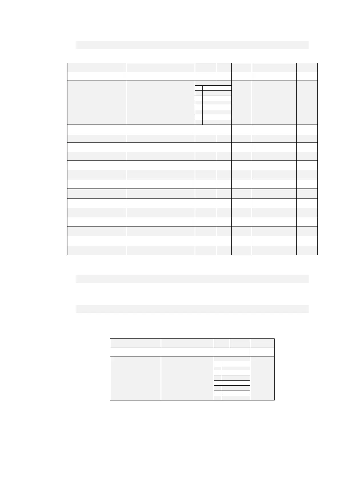
Name Description Min Max Default UM Scale
ID_CANOPEN P162 - CAN BUS node ID 1 127 1 1
CANOPEN_BAUD_SEL C48 - CAN Baud rate
Range
0 1
0 1 M
1 800 k
2 500 k
3 250 k
4 125 k
5 50 k
6 20 k
7 10 k
EN_FLDBUS_REF
P247 - Enable FIELD-BUS
reference values
0 1 0 1
PRC_T_REF_FLDBUS D69 - Fieldbus Torque reference -400 400 0 % MOT_T_NOM 40.96
PRC_T_MAX_FLDBUS
D71 - Fieldbus Torque Max
reference
-400 400 0 % MOT_T_NOM 40.96
PRC_SPD_REF_FLDBUS D75 - Fieldbus Speed reference -100 100 0 % MOT_SPD_MAX 163.84
SPD_REF_PULS_FLDBUS
D78 - Fieldbus Speed Reference in
Pulses
0 Pulses per Tpwm 1
PRC_APP_T_REF
D10 - Torque reference value
(application generated)
-100 100 0 % MOT_T_NOM 40.96
PRC_APP_T_MAX
D32 - Maximum torque imposed
(application generated)
-100 100 0 % MOT_T_NOM 40.96
PRC_APP_SPD_REF
D33 - Speed reference (application
generated)
-100 100 0 % MOT_SPD_MAX 163.84
PRC_APP_FRQ_SPD_REF
D14 - Frequency speed reference
value (application generated)
-100 100 0 % MOT_SPD_MAX 163.84
EN_SYNC_REG
C23 - Enable CANOpen SYNC
traking loop
0 1 0 1
SYNC_REG_KP
P11 - CanOpen SYNC loop
regulator Proportional gain
0 200 5 1
SYNC_REG_TA
P12 - CanOpen SYNC loop
regulator lead time constant
0
2000
0
400 1
SYNC_DELAY
D57 - Delay from SYNC reception
to Speed routine execution
0 us 1
PWM_SYNC_OFFSET
D58 - PWM offset for SYNC delay
control
0 pulses 1
4.2.1 CONFIGURATION OF THE APPLICATION
4.2.1.1 CONFIGURATION OF THE NODE
The drive configuration as CAN node includes the use of the following customer parameters ( of
conventional use ):
Name Description Min Max Default
ID_CANOPEN P162 - CAN BUS node ID 1 127 1
CANOPEN_BAUD_SEL C48 - CAN Baud rate
Range
0
0 1 M
1 800 k
2 500 k
3 250 k
4 125 k
5 50 k
6 20 k
7 10 k
These parameters must be rightly configured and saved in the permanent memory of the
drive (C63=1). At start up these data are considered and become operating.