63
User’s manual
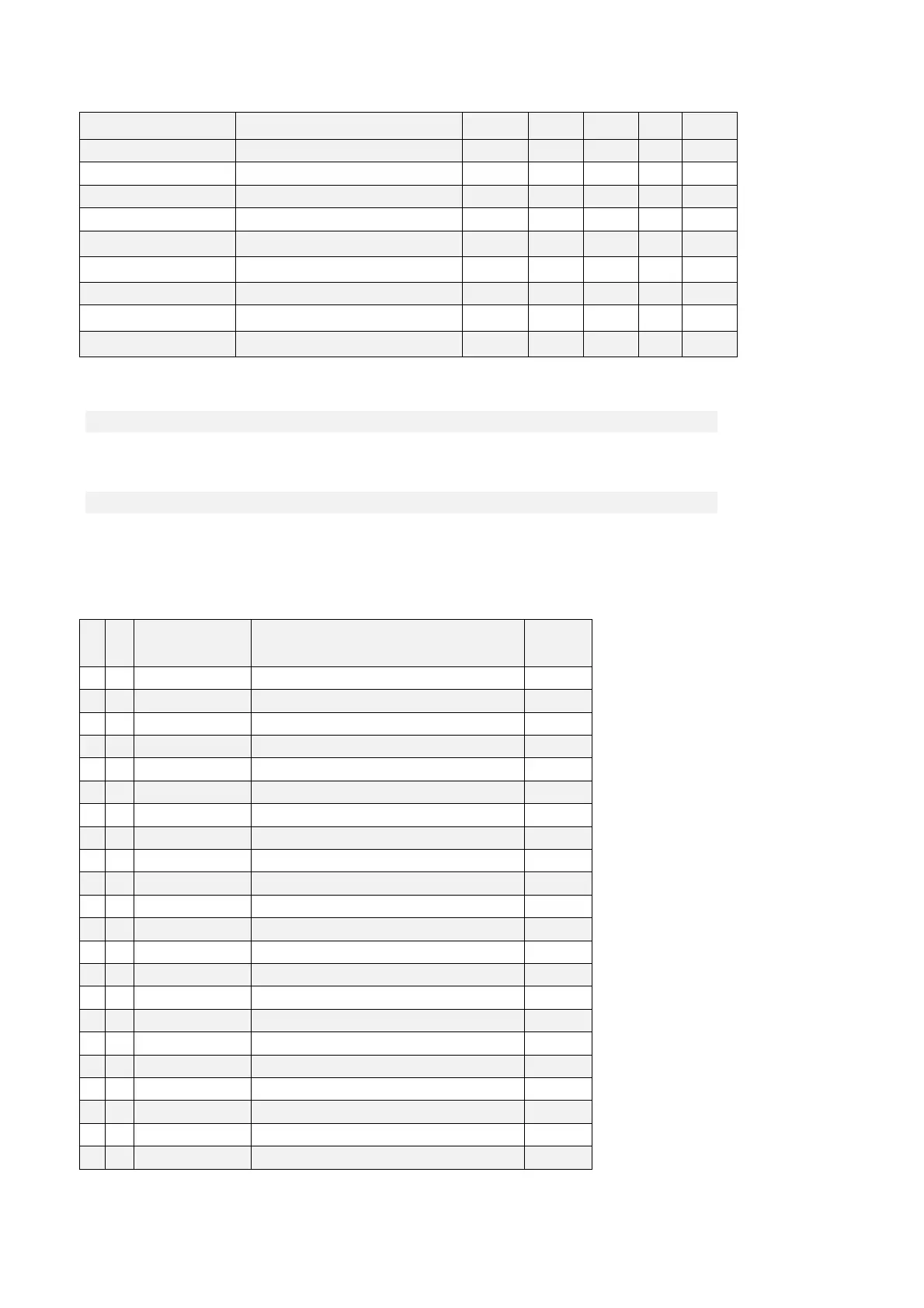
Name Description Min Max Default UM Scale
OFFSET_SIN_SENS2 P08 - Second sensor sine offset -16383 16383 0 1
OFFSET_COS_SENS2 P09 - Second sensor cosine offset -16383 16383 0 1
HW_SENSOR2 D62 - Sensor2 presence 0 1
SENS2_SPD D51 - Second sensor rotation speed 0 rpm 1
SENS2_TURN_POS
D52 - Second sensor Absolute mechanical
position (on current revolution)
0
1638
4
1
SENS2_N_TURN
D53 - Second sensor Number of
revolutions
0
1638
4
1
SENS2_FRQ_IN D54 - Second sensor Frequency input 0 KHz 16
SENS2_ZERO_TOP D56 - Sensor2 Zero Top 0
pulse
s
1
EN_SINCOS_PREC_POS
C70 - Enable SinCos Analog-Digital
compensation into position
0 1 0 1
3.2 OUTPUT
3.2.1 DIGITAL OUTPUT CONFIGURATIONS
The control can have up to 4 optically insulated digital outputs (L.O.1 … L.O.4) whose logic functions
can be configured as active high (H) by means of connection C10
÷ C13.
The following table shows the logic functions managed by standard application:
NAME OUTPUT LOGIC FUNCTIONS
DEFAULT
OUTPUT
O 00 OD_DRV_READY Drive ready L.O.2
O 01 OD_ALR_KT_MOT Moto thermal alarm
O 02 OD_SPD_OVR_MIN Speed exceed minimum L.O.4
O 03 OD_DRV_RUN Drive running L.O.1
O 04 OD_RUN_CW CW / CCW
O 05 OD_K_I_TRQ Current/torque relay
O 06 OD_END_RAMP End of ramp L.O.3
O 07 OD_LIM_I Drive at current limit
O 08 OD_LIM_TRQ Drive at torque limit
O 09 OD_ERR_INS Tracking incremental error > threshold (P37 ane P39)
O 10 OD_PREC_OK Power soft-start active
O 11 OD_BRK Braking active
O 12 OD_POW_OFF No mains power
O 13 OD_BUS_RIG Bus regeneration enable (Support 1 )
O 14 OD_IT_OVR Motor thermal current above threshold (P96)
O 15 OD_KT_DRV Radiator overheating (higher than P120 threshold)
O 16 OD_SPD_OK Speed reached (absolute value higher than P47)
O 17 OD_NO_POW_ACC Power electronic card not supplied
O 18
O 19 OD_POS_INI_POL Regulation card supplied and DSP not in reset state
O 20 SENS1 Absolute position available
O 21 Motor holding brake