94
5.3 DIGITAL COMMANDS AND CONTROL
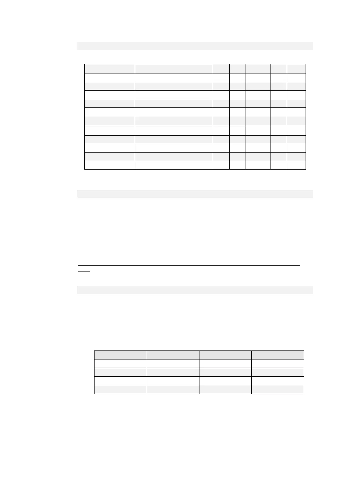
Name Description Min Max Default UM Scale
SW_RUN_CMD C21 - Run software enable 0 1 1 1
EN_STOP_MIN_SPD C28 - Stop with minimum speed 0 1 0 1
DRV_SW_EN C29 - Drive software enable 0 1 1 1
ALL_RESET C30 - Reset alarms 0 1 0 1
ALL_COUNT_RESET C44 - Reset alarm counters 0 2 0 1
EN_BRAKE_R_PROT
C71 - Enable braking resistance
protection
0 1 0 1
EN_STO_ONLY_SIG
C73 - Enable Safety STOP only like
signaling
0 1 0 1
EN_BOOT C98 - Enable boot mode 0 1 0 1
SPD_ISR D45 - Speed routine duration 0 us 64
I_ISR D46 - Current routine duration 0 us 64
SPD_ISR D45 - Speed routine duration 0 us 64
5.3.1 DRIVE READY
The Drive Ready condition (o.L.0=H) is given by alarms are not active and at the same time both the
software and hardware enables:
* The software enable, given by state of the connection C29, (C29=1 of default).
* The external enable (the function of the input is assigned to the default input L.I.2)
If an enable is missing or an alarm is active, the ready drive signal goes into an non-active state
o.L.0=L and this state remains until the causes that brought about the alarm conditions are removed
and the alarms are reset. An alarm reset can be achieved by activating the function “Alarm reset”
that, by default, is assigned to input L.1 (or setting C30=1).
Keep in mind that the “Alarm reset” is achieved by the active front of the signal, not on the active
level.
5.3.2 DRIVE SWITCH ON / RUN
When the drive is “Ready to switch on / RUN” o.L.0=H, motor may start running “Drive switch on/run”
o.L.3=H, by activating both the hardware and software switch on enables:
* Function “Logic switch on/RUN input” (default input 4 assigned) RUN=H
* Software switch on/RUN C21 (C21=1) is active by default.
Switch on/RUN disable and enable (from STOP offline, to RUN online) is given by the logic of the
following table:
Drive ready o.L.0 Switch on / RUN C21 ON-LINE
L X X L
H L X L
H X 0 L
H H 1 H
It is mentioned that the input function “Switch on/RUN input” can given also via serial line or field-bus.
See for details the Standard Application Manual.