77
User’s manual
4.1.2 MANAGED SERVICES
The drive represents the slave in the communication : this means that it is only able to answer to
messages received if its address (settable in P92) corresponds with the one indicated in the message
itself. If the address is wrong or there is an error of communication in CRC, the drive will not send any
answer, as the protocol requires.
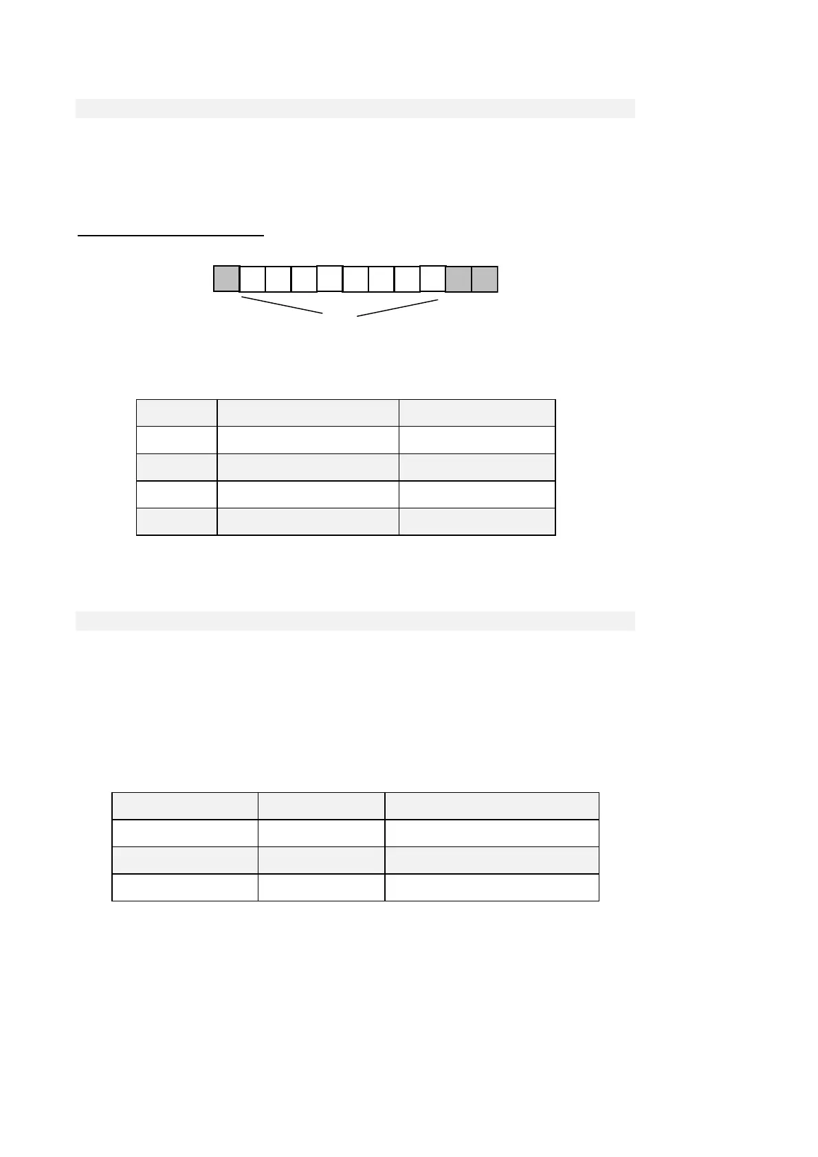
Every word transmitted is composed by 11 bit : 1 bit for start, 8 bit for the data and 1-2 bit for stop.
The parity check is not supported.
Start
Stop
Dato
The Modbus protocol requires a long functions series; our application requires less than these : in the
following table you can find the implemented functions and their codification :
Code Function Description
1 Read Coil Status Reading of digital input/output
03 Read Holding Registers Reading of memorised data
15 Force Multiple Coils Writing of digital inputs
16 Preset Multiple Registers Writing of memorised data
Hereinafter you can find the description of the action and of the related address of each function.
4.1.2.1 01 READ COIL STATUS
This function allows the user to read the status of the digital inputs and outputs.
It is important to underline that the standard management of the digital inputs requires that the RUN
enable must be given both via terminal board and via serial line; all the other inputs instead can be
commanded by one of the two ways just listed. The default RUN input from the serial line is high
while all the others are low: in this way the user who is not using it, can have the total control of
digital inputs from the terminal board.
Thanks to Read Coil Status function it is possible to read the status of the digital inputs and related
outputs you are interested in, just specifying the correct address written in the following table :
starting address(hex) Max number of data Description
0300 32 Digital input logical functions
0320 32 Standard digital outputs logical functions
0340 32 Applicative digital output logical functions
The order number of the inputs and the outputs is the one specified in the related tables (see specific
description of the control’s core) .