7
User’s manual
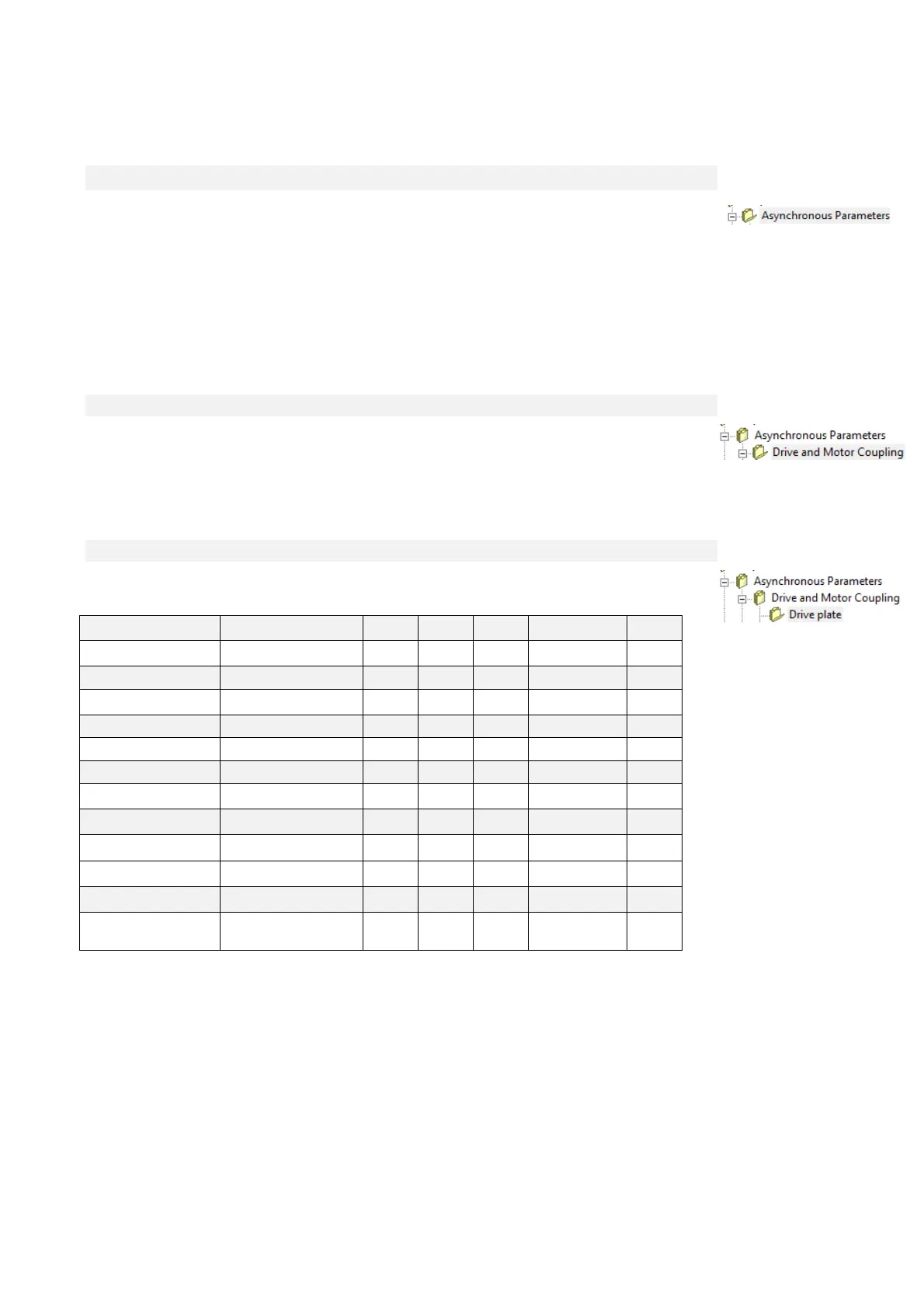
2 ASYNCHRONOUS PARAMETERS
The “Asyncrhonous Parameters” are used to control the current or speed of a feedback vector
induction motor. The speed and current reference values are generated by the application. See the
application parameters for further information. As an absolute position value is not required for the
sensors (managed with an optional internal electronic board) incremental TTL Encoders and
incremental Sin/Cos Encoders may be used. Absolute sensors such as Resolver can also be used,
as can digital sensors such as Endat or Hiperface if required.
The “Asyncrhonous Parameters” also manages the auto-tuning test, which is crucial if the control is
to adapt perfectly to the motor and to ensure excellent dynamic performance all-round.
2.1 DRIVE AND MOTOR COUPLING
This section is usefull during motor start-up to obtain the best coupling between drive and
motor. It’s very important to follow the correct sequence explained in the next paragraphs
2.1.1 DRIVE PLATE
Name Description Min Max Default UM Scale
MAIN_SUPPLY
P87 - Main Supply
voltage
180.0 780.0 400 V rms 10
DRV_I_NOM P53 - Rated drive current 0.0 3000.0 0 A 10
DRV_I_PEAK
P113 - Maximum drive
current
0.0 3000.0 0 A 10
I_OVR_LOAD_SEL C56 - Current overload 0 3 3 1
PRC_DRV_I_MAX P103 - Drive limit current 0.0 800.0 200 % DRV_I_NOM 40.96
DRV_F_PWM P101 - PWM frequency 1000 16000 5000 Hz 1
DRV_F_PWM_CARATT
P156 - PWM frequency
for drive definition
1000 16000 5000 Hz 1
DRV_E_CARATT
P167 - Characterization
voltage
200.0 690.0 400 V rms 10
DEAD_TIME
P157 - Dead time
duration
0.0 20.0 4 µs 10
T_RAD
P104 - Radiator time
constant
10.0 360.0 80 s 10
T_JUNC
P116 - Junction time
constant
0.1 10.0 3.5 s 10
OVR_LOAD_T_ENV
P155 - Ambient
temperature reference
value during overload
0.0 150.0 40 °C 10
This parameters are related to the drive characteristic. The user has to set only the main supply
voltage and select the current overload.