19
User’s manual
o If A14 code=0 is enabled, connections U,V,W do not match the internal phases of
the drive. Invert two phases and repeat the test.
o If A15 code=3 is enabled, the values set do not comply with the motor pole and
sensor settings.
At the end of the test, check parameter P79 as it may give some indication as to the problem. See
the “Feedback Option” file for the meaning of P79 as it depends on which sensor is used.
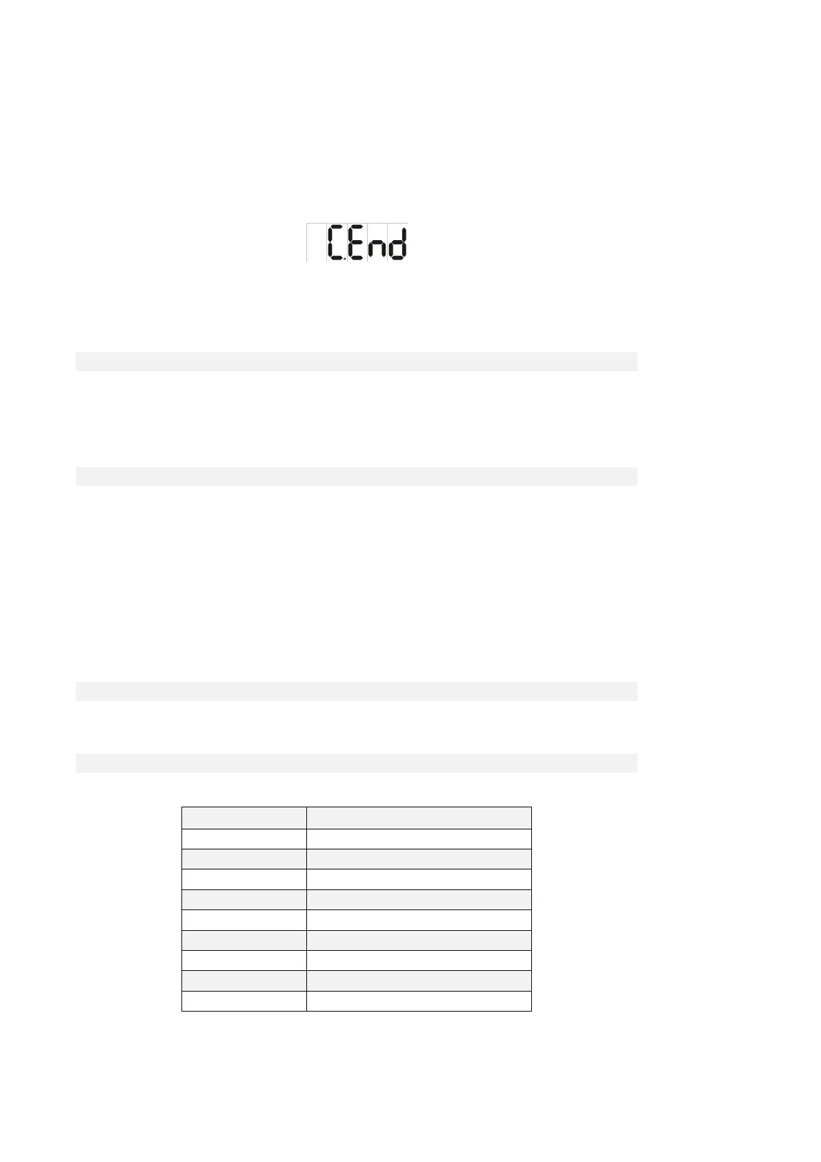
The test is successful if this setting appears on the display:
and the drive does not trigger an alarm.
Now disable RUN by setting its digital input to 0 or clearing C21.
The subsequent tests can now be carried out.
2.1.4.6.2 FINE SENSOR SETUP
After the first part of the autotunning, in some case, is possible to set some parametes regarding the
sensor to obtain a better system performance.
Dopo la prima parte dell’autotaratura, in alcuni casi, si possono settare alcuni parametri relativi al
sensore in modo da migliorare le prestazione del sistema:
2.1.4.6.3 ENCODER TIME DECODE
By default (C74=0) the speed is measuring counting the number of pulses in the PWM period.
This produces a poor resolution especially at low speed and the consequent need of signal filtering
(see the related core document, P33 parameter of speed regulator).
Setting C74=1 the speed calculation is done measuring the time between one Encoder pulse to the
other.
This technique has a maximum resolution of 12.5 ns, so the measure can be very accurate.
The Encoder time decode needs Incremental Encoder pulses with duty-cycle of 50%, a correct
pulses time distribution and the cables would be shielded very well
2.1.5 IDENTIFYING MODELS OF INDUCTION MOTOR
2.1.5.1 MOTOR AUTO-TUNING PARAMETERS
Name Description
PRC_MOT_T_MAX P41 - Maximum torque at full load
MOT_COS_PHI P66 - Nominal power factor
PRC_MOT_I_T_NOM P72 - Nominal torque current
PRC_MOT_I_FLX_NOM P73 - Nominal flux current
T_ROTOR P74 - Rotor time constant Tr
T_STATOR P75 - Stator time constant Ts
PRC_DELTA_VRS P76 - Voltage drop due to stator resistor
PRC_DELTA_VLS P77 - Voltage drop due to leakage inductance
MOT_T_NOM P78 - Nominal motor torque
These parameters are extremely important for modelling the motor correctly so that it can be used to
its full potential. The best procedure for obtaining the correct values is the “Auto-tuning test”, which