62
NB: pay particular attention to the fact that it is absolutely not possible to assign the same
logic function to two different logic inputs: after changing the connection value that sets a
determined input, check that the value has been accepted, if not check that another has not
already been allocated to that input. In order to disable a logic input it’s necessary to assign
to it the logic function -1 : this is the only value that can be assigned to more than one inputs.
For example, to assign a specific logic function to logic input 1 you must first write the desired logic
number for connection I01 :
I01 = 14 Æ logic input 1 can be used to enable Fieldbus references
The logic functions that have been configured become active ( H ) when the input level is at high
status (20V < V < 28V), and there is a 2.2ms hardware filter. With the connection C79 it’s possible to
enable the active logic low state for a particular digital input, it’s necessary to sum 2 to the power of
ordinal input number:
For example to set digital inputs I0 and I3 to active low state, set:
922C79
30
=+=
The functions that have not been assigned assume default value ; for example, if the function
“external enable“ is not assigned it becomes, as default, “active ( H )” so the converter is as if there
were no assent from the field
3.1.4.1 INPUT LOGIC FUNCTIONS SET IN OTHER WAYS
In reality the input logic functions can also be set by serial connection and by fieldbus, with the
following logic:
o I00 Run : stands alone, it has to be confirmed by terminal board inputs, by the serial
and by the fieldbus, though in the case of the latter the default is active and
so, if unaltered, controls only the terminal board input.
o I01
÷ I31: is the parallel of the corresponding functions that can be set at the terminal
board, the serial or the fieldbus
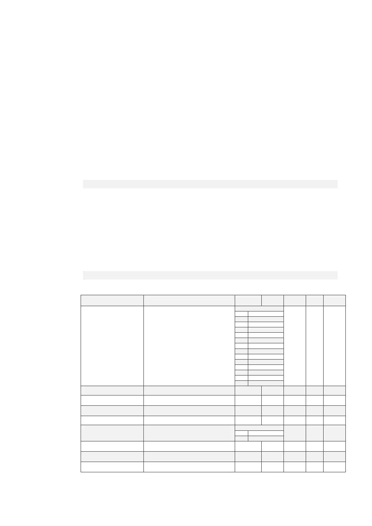
3.1.5 SECOND SENSOR
Name Description Min Max Default UM Scale
SENSOR2_SEL C17 - Sensor2 selection
Range
0 1
0
1 Encoder
2
3
4 Resolver
5 Resolver RDC
6
7
8 Sin/Cos incr
9
10 Endat 1317
11 Endat 1329
12
13
RES2_POLE P16 - Number of absolute sensor2 poles 1 160 2 1
ENC2_PPR
P17 - Number of encoder2
pulses/revolution
0 60000 1024
pulse
s/rev
1
EN_TIME_DEC_ENC2
C18 - Enable incremental encoder2 time
decode
0 1 0 1
EN_INV_POS2_DIR C20 - Invert sensor2 positive cyclic versus 0 1 0 1
EN_SENSOR2_TUNE C19 - Enable sensor2 auto-tuning
Range
0 1 0 No
1 Yes
RES2_TRACK_LOOP_BW
P48 - Tracking loop bandwidth direct
decoding of resolver2
100 10000 1800 rad/s 1
RES2_TRACK_LOOP_DAM
P
P49 - Damp factor Traking loop resolver2 0.00 5.00 0.71 100
KP_SENS2
P07 - Second sensor amplitude
compensation
0.0 200.0 100 % 163.84