83
User’s manual
Set the number of mapped objects in Sub-Index 0 to be equal to zero
Configure the addresses of all mapped objects
Indicate the correct number of mapped objects in Sub-Index 0
4.2.3 EMERGENCY OBJECT (EMCY)
The emergency object is transmitted by the drive when a new enabled alarm comes trough or when
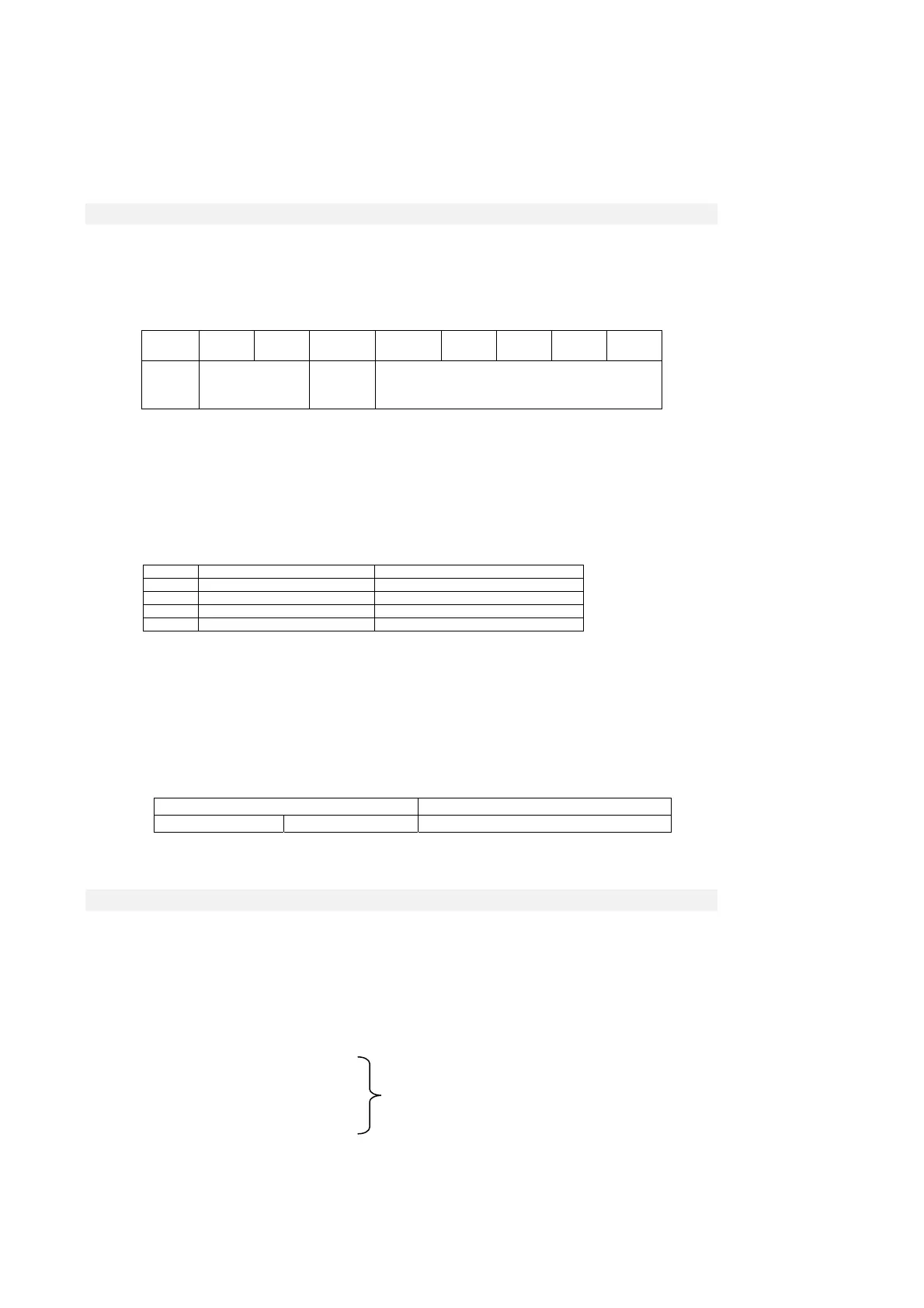
one or more alarms are reset. The Emergency telegram is made by 8byte as shown in the following
table:
Byte 0 1 2 3 4 5 6 7
meaning
Emergency
Error Code
Error
register
Manufacturer specific
alarms LSB –MSB
In our implementation only two codes of the error code are implemented :
00xx = Error Reset or No Error
10xx = Generic Error
Speaking of the Error register (object 1001h), the following bits are managed corresponding to the
following alarms:
Bit Meaning Corresponding alarms
0 General error all
1 Current A3
2 Voltage A10 - A11 -A13
3 temperature A4 - A5 - A6
In Manufacturer specific only the bytes 3 and 4 are assigned which contain the state of the various
alarms of the drive. Further 3 bytes for the transmission of possible other user’s data are available.
The management of 1003h “pre-defined error field “ object memorises the chronology of the alarm
events (from start up of the drive) up to a maximum of 32 elements.
At every new alarm event 4 bytes are memorised, 2 are mandatory and correspond to the Error
Code; the other 2 are Manufacturer specific and in our specific case correspond to the state of all the
drive alarms.
MSB LSB
Additional information Error code
alarms MSB alarms LSB Error code MSB Error code LSB
4.2.4 NETWORK MANAGEMENT OBJECTS (NMT)
This function allows the NMT master to check and set the state to every NMT slave.
All the services of Module Control and also the Node Guarding Protocol which uses the COB-ID =
700h + ID CAN node are implemented: this allows the slave to communicate that the bootup ended
and the pre-operational modality is active, thus the master can interrogate the different slaves with an
RTR.
The Life guarding function is implemented as well: the drive (NMT slave) can be set up by the
objects:
100Ch Guard time in ms
100Dh Life time factor (multiplier factor)
their product yields the Node life time
note: node life time is internally saturated in the
period time of 32767/fpwm sec.