67
User’s manual
3.2.3 FREQUENCY OUTPUT
With C52 I possible select the signal for the frequency output as indicated in the follow table:
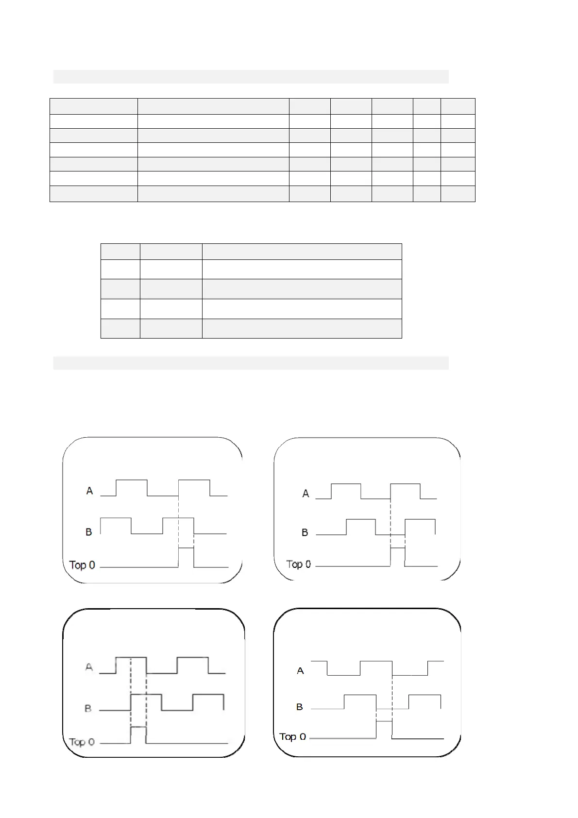
3.2.3.1 SIMULATED ENCODER SIGNALS
The frequency of the output signals depends on the motor revolutions, the number of sensor poles
and the selection made (see connection C51 in the core file) and their behaviour in time depends on
rotation sense (CW or CCW) and on C50 as shown in the figures below
Name Description Min Max Default UM Scale
ENC_OUT_ZERO_TOP C49 - TOP zero phase for simulated encoder 0 3 0 1
ENC_OUT_DIR C50 - Invert channel B simulated encoder 0 1 0 1
ENC_OUT_PPR_SEL C51 - Choose pulses ev. simulated encoder 0 11 5 1
ENC_OUT_SEL C52 - Simulated encoder selection 0 3 0 1
OPD_ENC_OUT_SEL C54 - Incremental/absolute Simulated Encoder 0 2 0 1
PRC_ENC_OUT_LOOP
P124 - Simulated encoder Kv gain
multiplication coeff.
0.0 100.0 100 % 327.67
C52 Value Description
0 OPD_ENC_OUT
The frequency output is the simulated encoder that can be
configures conforming the follow paragraph
1 SENS1
The frequency output is the squared signal from the motor
speed (sensor 1)
2 SENS2
The frequency output is the squared signal from the speed
sensor 2
3 FRQ_IN
The frequency output is the squared signal from the frequency
input
d21>0 C50=0 d21>0 C50=1
d21<0 C50=0
d21<0 C50=1