68
The simulated encoder outputs are all driven by a “LINE DRIVER”. Their level in the standard drive
version is referred to +5V and then it is connected to the internal supply (TTL +5V).
In option (to be requested in the ordering) there is the possibility to refer the signal level to an
external supply whose value must be between +5V and +24V, connection on terminal 5 and 6.
In the connected device it is better to use a differential input to avoid loops with the 0V wire, to limit
noise effects it is better to load this input (10mA max).
It is necessary to use a twisted shielded cable
to make a proper connection.
WARNING: the external power supply GND is connected with the 0V of the drive (it is not
optoisolated).
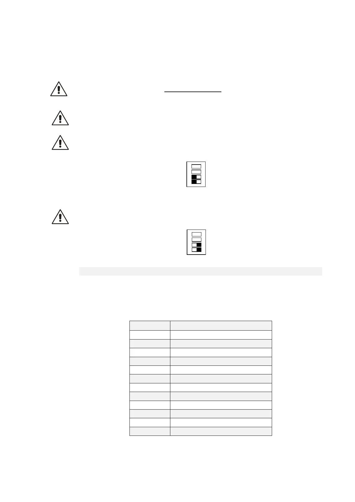
WARNING: for the encoder simulation with internal supply (standard drive version) you must
not connect the terminal 5 (Vccin), because it could seriously damage the drive, and set the
SW1 switch as indicated in the follow image.
WARNING: for the encoder simulation with external supply, you must connect the terminal 5
(Vccin) and 6 (GND) and set the SW1 switch as indicated in the follow image.
3.2.3.2 CONFIGURATION OF THE ENCODER SIMULATION OUTPUT
The two bidirectional simulation encoder channels could have a number of pulses per motor
revolution selectable with C51 according to the following table, that also depends on the number of
sensor polar couples:
C51 Pul/rev motor/(P68/2)
0 0
1 64
2 128
3 256
4 512
5 1024
6 2048
7 4096
8 8192
9 16384
10 32768
11 65536
ON
SW1
1
ON
SW1
1