9
User’s manual
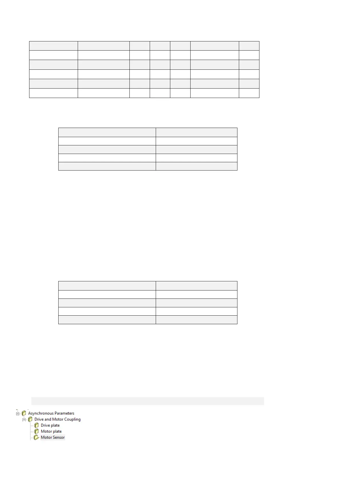
Name Description Min Max Default UM Scale
MOT_SPD_MAX
P65 - Max. operating
speed (n MAX)
50 60000 2000 RPM 1
MOT_COS_PHI
P66 - Nominal power
factor
0.500 1.000 0.894 1000
MOT_POLE_NUM
P67 - Number of motor
poles
1 12 4 1
PRC_MOT_I_THERM
P70 - Motor thermal
current
10.0 110.0 100 % PRC_MOT_I_NOM 10
MOT_TF_THERM
P71 - Motor thermal time
constant
30 2400 180 s 1
Setting the parameters that establish the exact type of motor used is important if the drive is to run
correctly. These parameters are:
Name Description
PRC_MOT_I_NOM P61 - Rated motor current ( I NOM MOT)
MOT_V_NOM P62 - Rated motor voltage
MOT_F_NOM P63 - Rated motor frequency
MOT_POLE_NUM P67 - Number of motor poles
These parameters are fundamental in that they are the basis of all the motor operating
characteristics: frequency, speed, voltage, current, torque and thermal protection.
P62 and P63 can be read directly on the motor rating plate and P61 can be calculated with the
following formula:
P61 = (Inom_motor *100.0))/(Inom_drive)
Example: Drive: OPEN 22
Inom_drive = 22A overload 200%
Motor: MEC series, Vn = 380V, f = 50Hz, Inom_motore = 20A,
P61 = (20*100)/22 = 90.9%
P62 = 380.0
P63 = 50.0
There are also parameters that establish the maximum values for voltage, thermal current and
operating speed:
Name Description
PRC_MOT_V_MAX P64 - Max. operating voltage
MOT_SPD_MAX P65 - Max. operating speed (n MAX)
PRC_MOT_I_THERM P70 - Motor thermal current
MOT_TF_THERM P71 - Motor thermal time constant
These important parameters must be specified alongside the exact characteristics of the feedback
sensor used. Once the sensor has been established, the “Sensor and motor pole tests” can be
carried out (enabled with C41) which will confirm that the parameters have been set correctly.
2.1.3 MOTOR SENSOR