23
User’s manual
Name Description
PRC_MOT_T_MAX P41 - Maximum torque at full load
T_ROTOR P74 - Rotor time constant Tr
T_STATOR P75 - Stator time constant Ts
MOT_T_NOM P78 - Nominal motor torque
V_REG_KP P80 - Kpi voltage regulator proportional gain
V_REG_TF P82 - Tfi voltage regulator (filter) time constant
I_REG_TI P84 - Tic current regulator lead time constant
I_REG_TF P85 - Tfc current regulator (filter) time constant
By the end of this test, the current and flow regulators will have been completely self-set and made
compatible with the motor connected to the drive.
These readings also help estimate the Maximum motor torque (P41) which is important if the motor
flux has to be considerably weakened.
The speed regulator gains are set with the default values so that the user can set the most suitable
gains for the applications. The speed loop bandwidth depends heavily on the overall load inertia, thus
high frequency values can only be obtained if the motor-load coupling has no elasticity or mechanical
play and if the speed sensor resolution is good enough not to introduce too much noise.
Name Description
END_SPD_REG_KP P31 - KpV final speed regulator proportional gain
END_SPD_REG_TI P32 - TiV final speed regulator lead time constant
END_SPD_REG_TF P33 - TfV final speed regulator (filter) time constant
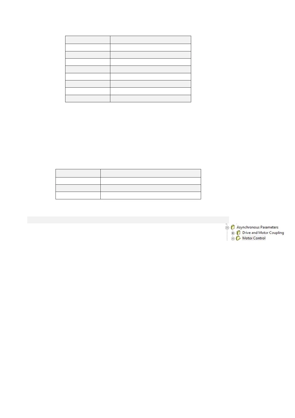
2.2 MOTOR CONTROL
The regulation system consists of a speed regulation loop and a flux or voltage regulation loop
according to drive operation. These loops manage the reference values from the application and
generate reference values for the internal torque and flux current loops.
All the loops are controlled by integral proportional regulators with an error signal filter and work with
normalized signals so that the regulation constants are as independent as possible from the size of
the motor in relation to the drive and from the system mechanics. An additional space loop that
overlaps the speed loop can also be enabled.