69
User’s manual
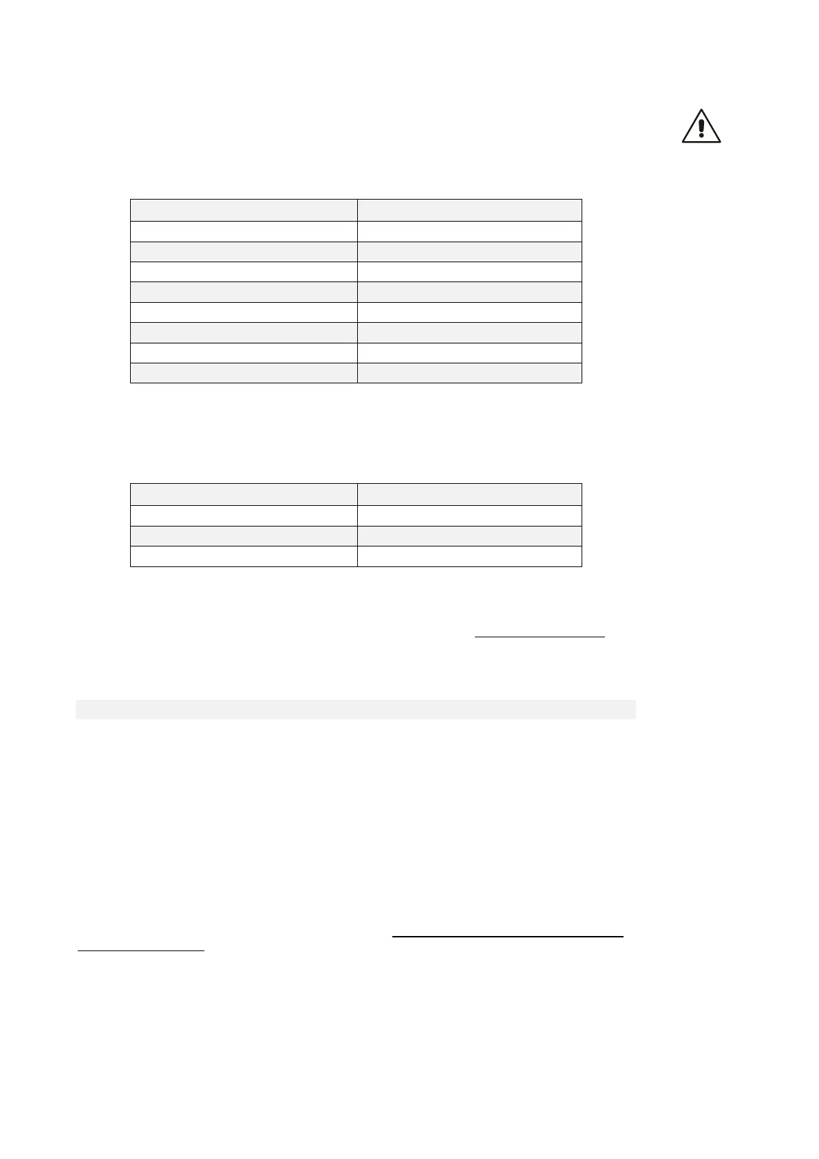
WARNING: The choice of the number of pulses for revolution depends on the maximum speed
and the number of sensor polar couples (P68/2). In the following table are reported this
limitation. If it is selected a number of pulses too high compared with the maximum speed it is
triggered the alarm A15 code =1.
Maximum speed (rpm) x P68/2 Pul/rev motor/(P68/2)
400 65536
800 32768
1600 16384
3200 8192
6400 4096
12800 2048
25600 1024
32767 512
NB: In the particular case of Resolver decoded with RDC19224, the choice of the number of pulses
for revolution depends on the maximum speed and the number of sensor polar couples (P68/2) in
this way:
Maximum speed (rpm) x P68/2 Pul/rev motor/(P68/2)
1500 16384
6000 4096
24000 1024
The default value is C51=5 correspond to 1024 pul/rev.
As can be seen, the number of pulses also depends on the number of sensor poles which are set in
parameter P68, and, in particular, the above-mentioned values are valid if the sensor is two-pole
.
The pulse output is controlled by a line driver (ET 7272); the limitation of the number of pulses
regards the maximum speed is done for limit the maximum frequency for channel to 437KHz.
3.2.3.3 INCREMENTAL OR ABSOLUTE SIMULATED ENCODER
The C54 connection allows to select two different modes of working for simulated encoder:
Incremental Simulated Encoder C54=0 (default): in this mode the simulated encoder
channels follow the motor rotation in incremental way and the third channel (zero pulse)
looses of meaning
Absolute Simulated Encoder C54=1: in this mode also the third channel (zero pulse) is
managed but in the first edge of sensor zero pulse there will be a correction into simulated
encoder channels.
This choice is significant only for sensors with a zero pulse (Encoder, Encoder and Hall sensors,
Sin/Cos Encoder), in the other case (Resolver, Endat) the Simulated Encoder is always absolute,
without any correction into simulated encoder channels.
The third channel generates a number of zero pulses in phase with channel A, equal to the number of
sensor poles divided by two (P68/2); in particular there is one single zero pulse per motor revolution
with a two-pole sensor.
The position of the zero pulse depends on the fit of the sensor on the drive shaft; with reference to
the original position, decoding the zero of the sensor position, this position may be changed with
jumps of 90° electrical (with reference to the sensor) by means of connection C49 according to the
following table: