10
MP00000B00 V_2.6
3.1- DENOMINAZIONE DELL’APPA-
RECCHIO
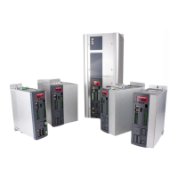
L’apparecchio in oggetto è così denominato:
Azionamento OPDE
3.1- NAME OF THE DEVICE
The device referred to here in is called:
5
V
0
Livello / Level
5= livello 5/ 5 level
OPDE
D1= OPDE
Tipo / Type
A= A.F.E. (Active Front End)
B= Brushless / Brushless sensorless
C = Chopper
M= Inverter con sincronizzante (Starter)
V= Field oriented control + Vector V/f
Taglia / Size (1)
003= 3A (1,5 kW) - 007= 7A (3 kW) - 012= 12A (5,5 kW) - 015= 15A (7,5 kW) - 022= 22A (11 kW)
032= 32A (15 kW) - A40= 40A (20 kW) - A48= 48A (22 kW) - A60= 60A (30 kW) - 070= 70A (37 kW)
090= 90A (45 kW) - 110= 110A (55 kW) - 150= 150A (75 kW) - 175= 175A (90 kW) - 220= 220A (110 kW)
250= 250A (132 kW) - 310= 310A (160 kW) - 370= 370A (200 kW) - 460= 460A (250 kW) - 570= 570A (315kW)
Sovraccarico / Over-
load
X= Standard (5 kHz PWM) (Tutti i sovraccarichi possibili / All overload)
A= 8 kHz PWM - B= 4 kHz PWM - C= 3 kHz PWM - D= 2 kHz PWM
Tensione rete / Main
supply
3T= 380V trifase / 3 phase
3D= 310V VDC
5D= 560V VDC
Drive
A= Drive+Reg.—>24V ext. (case S-M-L-X) - B= Drive+Reg. —>24V ext.+STO (case S-M-L-XL)
C= Drive+Reg.—> Autofeed 24V int (case S-M-L-X) - H = Drive+Reg.—>24V ext (case 1) - F= Drive+Reg.—>
Autofeed + 24V ext. (case 1) G= Drive+Reg.—> Autofeed + 24V ext. +STO(case 1) - J = Drive+Reg.—>24V
ext. (case 2-3) - M= Drive+Reg.—> Autofeed +24V ext. + pred. STO (case 2-3)
Freno / Brake
0= NO
1= SI / YES
Sensore velocità 1 /
Speed sensor 1 (2)
0= Senza sensore / No feedback
B= Resolver
C= Resolver alta risoluzione / High resolution resolver
D= Incremental/absolute Sin/Cos
E= Endat - BISS (3)
F= Ingresso analogico ad alta risoluzione / High resolution
analog input
G= Encoder TTL + S.HALL standard
H= Encoder Hiperface / Hiperface encoder
L= Resolver DSUB-9 / DSUB-9 resolver
M= Out Encoder Simulato DSUB-9 / DSUB-9 Simu-
lated Out Encoder
Sensore velocità 2 /
Speed sensor 2 (2)
0= Senza sensore / No feedback
B= Resolver
C= Resolver alta risoluzione / High resolution resolver
D= Incremental/absolute Sin/Cos
E= Endat - BISS (3)
F= Ingresso analogico ad alta risoluzione / High resolu-
tion analog input
G= Encoder TTL + S.HALL standard
H= Encoder Hiperface / Hiperface encoder
L= Resolver DSUB-9 / DSUB-9 resolver
M= Out Encoder Simulato DSUB-9 / DSUB-9 Simu-
lated Out Encoder
Bus di campo / Field
I/O
Field 0= None - 1= Profibus - 3= Canbus - 4=Ethercat - 5= HSC (high speed communication) - X= pred Anybus
Personalizzazione /
Customer
V= TDE Standard version (lettera diversa si riferisce a personalizzazione specifica / a different letter metch a
specific costumization)
0= No - X= Display + I/O + RS485 Serial line
OPDE drive
(1) L’indicazione in kW è riferita ad una tensione di alimentazio-
ne di 400 VAC.
(2) Le schede di retroazione opzionali possono essere aggiunte
o cambiate anche dal cliente (v. par. 5.1)
(3) Specificare modello di sensore guardando paragrafo 5.3.6.
(1) kW is referred to a 400 VAC supply voltage.
(2) The optional feedback boards could be added or changed
by the customer (s. par. 5.1)
(3) Specify sensor model see in the 5.3.6 paragraph
3.2- CODIFICA OPDE
Di seguito viene descritto il codice OPDE nelle singole
lettere che troviamo nel campo “Type” della marcatura
CE / targa dati (v. par. 1.1).
3.2- OPDE CODE
Below is a description of the OPDE code, explaining
the meaning of each single letter appearing in the
“Type” field of the CE marking/data plate (s. par. 1.1).
D
1