71
MP00000B00 V_2.6
5.3.12 – CAN BUS
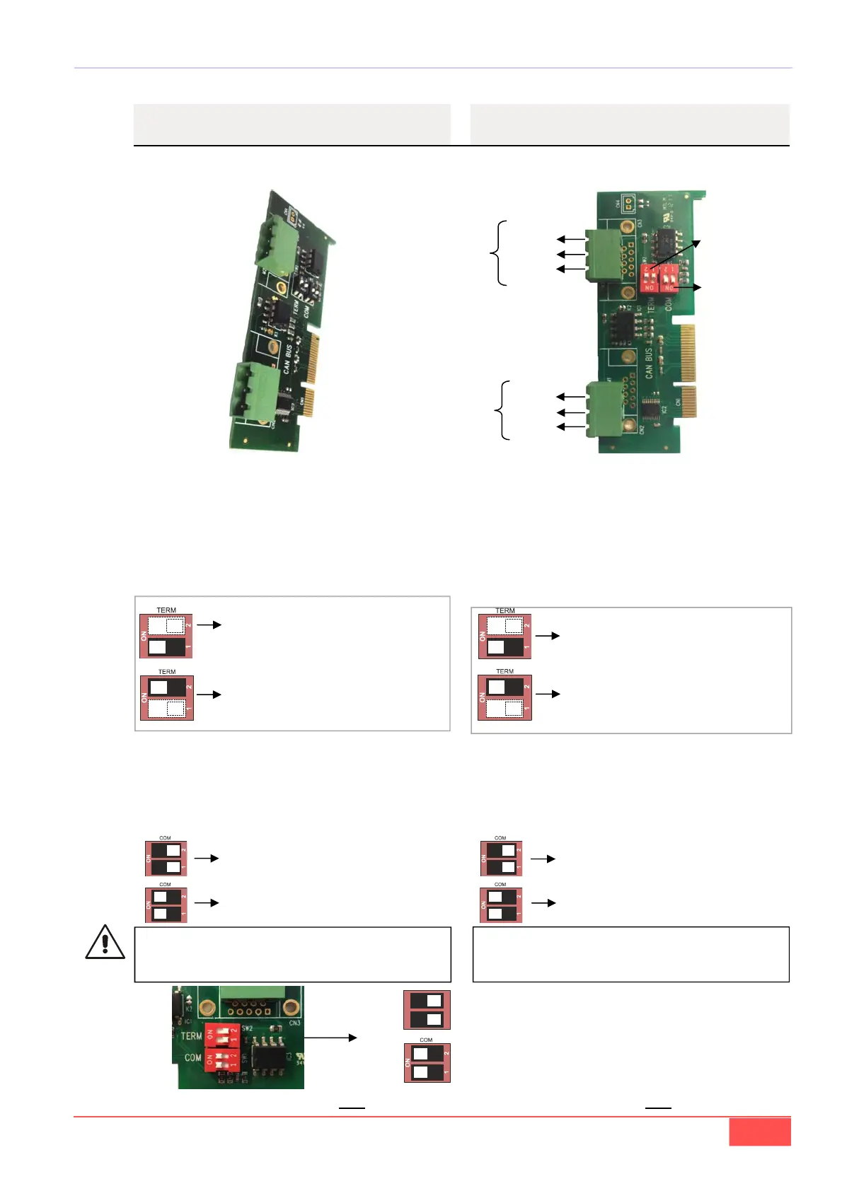
Viene di seguito riportata la piedinatura della scheda
opzionale per la comunicazione via CAN BUS
Sulla scheda inoltre sono previsti 2 dipswitch doppi
indicati come:
- TERM
- COM
I contatti del dipswitch “TERM” (uno per ogni connetto-
re can) se in posizione ON inseriscono la resistenza di
terminazione (120 ) tra CAN H e CAN L .
5.3.12 – CAN BUS
In the follow is indicated the pin signals position about
CAN BUS optional card
On the board are present 2 double dipswitch indicatet
as:
- TERM
- COM
The contact of “TERM” dipswitch (one for each CAN
connector) if in the ON position insert the resistor for-
termination (120 ) between CAN H and CAN L.
CAN L
CAN H
GND
BUS 2
(principale)/
(main)
BUS 1
I contatti del dipswitch “COM” accomunano i segnali
CAN L e CAN H dei due BUS in modo che i due con-
nettori possono essere usati uno come ingresso e l’al-
tro come uscita. “I due dipswitch vanno sempre posi-
zionati in coppia”
TERMinato BUS1
TERMinato BUS2
BUS1 non connesso con BUS2
BUS1 connesso con BUS2
Se BUS1 e BUS 2 sono connessi insieme, MAI
collegare entrambe le resistenze di terminazione
(dip–switch TERM)
CAN H
CAN L
GND
BUS1 TERMinated
BUS2 TERMinated
BUS1 not connected with BUS2
BUS1 connected with BUS2
If BUS1 and BUS 2 are connected together
NEVER connect both the terminal resistors
(TERM dip-switch)
The contact of “COM” dipswitch connect together the
CAN H and CAN L signals of the two BUSES, so, in
this way, is possible use one connector as input and
the other connector as output. “The two dipswitches
should always be positioned a couple”
DIPSWITCH
TERM
DIPSWITCH
COM
Settaggio di default/ Default setting
(BUS1 e BUS2 connessi insieme ma non
terminati / BUS1 and BUS2 connected to-
gether but not terminated)
ON
12
TERM
c
o
d
.
2
7
4
B
0
0
0
1
1
0
V
V
Qualsiasi manovra va effettuata solo a drive spento! / Any operation must be done only to drive off!