11
MP00000B00 V_2.6
3.3 - CODIFICA OPDE PER
APPLICAZIONI ENERGIE
ALTERNATIVE
3.3 - OPDE CODE FOR ENERGY
POWER APPLICATIONS
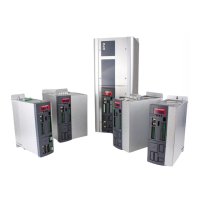
Oltre all’OPDE inverter standard è presente la linea di
inverter OPDE Energy ( brushless, asincrono, ecc..)
per applicazioni energie alternative. Di seguito viene
descritto il codice dell’inverter OPDE Energy nelle
singole lettere che troviamo nel campo “Type” della
marcatura CE / targa dati (v. par. 1.1).
In addition to OPDE standard inverter there is the line
OPDE Energy (brushless, asynchronous, ext..) for
energy power application. Below is a description of
the OPDE Energy inverter code , explaining the mea-
ning of each single letter appearing in the “Type” field
of the CE marking/data plate (s. par. 1.1).
V
0
Livello / Level
6= livello 6/ 6 level
OPDE
D1= OPDE
Tipo / Type
B= Brushless Energy / Brushless sensorless Energy
M= Inverter con sincronizzante Energy / Starter Energy
S= A.F.E. Energy
V= Field oriented control + Vector V/f Energy
Taglia / Size (1)
007= 7A - 015= 15A - 022= 22A - 032= 32A - A48= 48A - A60= 60A case S_M_L_XL
070= 79A - 090= 103A - 110= 110A - 150= 152A CASE 1
175= 195A - 220= 248A - 250= 282A CASE 2
310= 348A - 370= 414A - 460= 480A CASE 3
Sovraccarico / Over-
load
X= Standard (5 kHz PWM) (Tutti i sovraccarichi possibili / All overload)
C= 3 kHz PWM
Tensione rete / Main
supply
Drive
A = Drive+Reg.—>24V esterno / external 24V (case S_M_L_XL)
H = Drive+Reg.—>24V esterno / external 24V (case 1)
M = Drive+Reg.—>24V esterno / external 24V (case 2-3)
Freno / Brake
0= NO
1= SI / YES
Sensore velocità 1 /
Speed sensor 1 (2)
0= Senza sensore / No feedback
B= Resolver
C= Resolver alta risoluzione / High resolution resolver
D= Incremental/absolute Sin/Cos
E= Endat - BISS (3)
F= Ingresso analogico ad alta risoluzione / High resolution
analog input
G= Encoder TTL + S.HALL standard
H= Encoder Hiperface / Hiperface encoder
L= Resolver DSUB-9 / DSUB-9 resolver
M= Out Encoder Simulato DSUB-9 / DSUB-9
Simulated Out Encoder
Sensore velocità 2 /
Speed sensor 2 (2)
0= Senza sensore / No feedback
B= Resolver
C= Resolver alta risoluzione / High resolution resolver
D= Incremental/absolute Sin/Cos
E= Endat - BISS (3)
F= Ingresso analogico ad alta risoluzione / High resolution
analog input
G= Encoder TTL + S.HALL standard
H= Encoder Hiperface / Hiperface encoder
L= Resolver DSUB-9 / DSUB-9 resolver
M= Out Encoder Simulato DSUB-9 / DSUB-9
Simulated Out Encoder
Bus di campo / Field-
bus
0= No fieldbus - 1= Profibus - 2= DeviceNet - 3= Can Bus - 4= Ethercat - 5= Hsc (hight speed communication)
I/O
0= No - X= Display + I/O + RS485 Serial line
Field
Personalizzazione /
Customer
V= TDE Standard version (lettera diversa si riferisce a personalizzazione specifica / a different letter metch a
specific costumization)
5D= 560V VDC
(1) L’indicazione in kW è riferita ad una tensione di alimentazio-
ne di 400 VAC.
(2) Le schede di retroazione opzionali possono essere aggiunte
o cambiate anche dal cliente (v. par. 5.1)
(3) Specificare modello di sensore guardando paragrafo 5.3.6.
(1) kW is referred to a 400 VAC supply voltage.
(2) The optional feedback boards could be added or changed
by the customer (s. par. 5.1)
(3) Specify sensor model see in the 5.3.6 paragraph
5 D
6
D 1