46
MP00000B00 V_2.6
5.2.9- DISPOSIZIONI CONNESSIO-
NI DI POTENZA (RETE,
MOTORE)
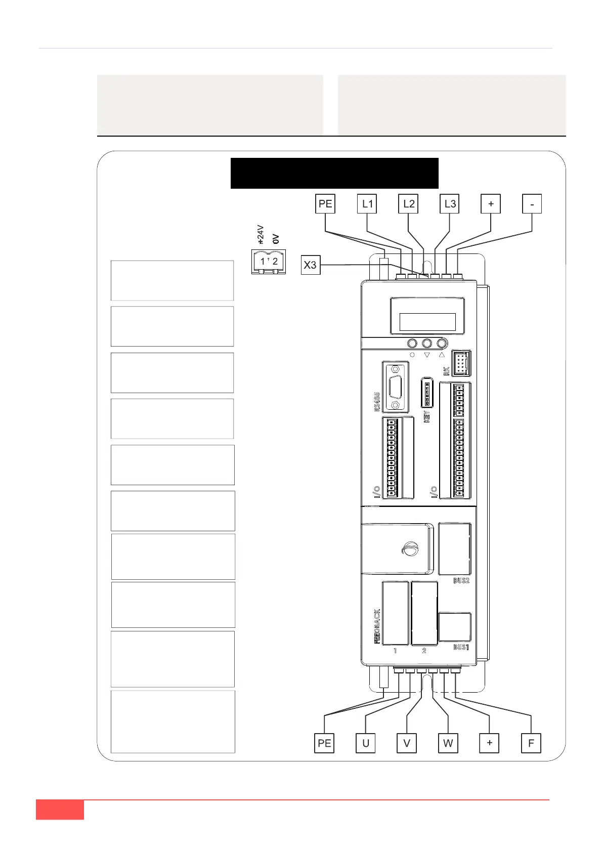
FIG. 11A (Collegamenti: potenza e controllo / Connections: Power and control)
5.2.9- POWER CONNECTIONS LAY-
OUT (MAINS, MOTOR)
Mod. 03A - 07A
“+” “-”: collegamento in
DC Bus
“+” “-”: DC Bus connection
L1-L2-L3: ingresso linea
U-V-W: uscita motore
L1-L2-L3: line input
U-V-W: motor output
“+” “F”: collegamento
resistenza frenatura
“+” “F”: Brake resistor con-
nection
X3: alimentazione scheda
regolazione (
obbligatoria
nella versione standard)
o
uscita +24V (v. par.5.2.7)
X3: regulation board supply
(obligatory in the standard
version)
or +24V output (s.
par. 5.2.7)
PE: collegamento cavo di
terra del motore e schermo
PE: Connection of PE and
shield