39
MP00000B00 V_2.6
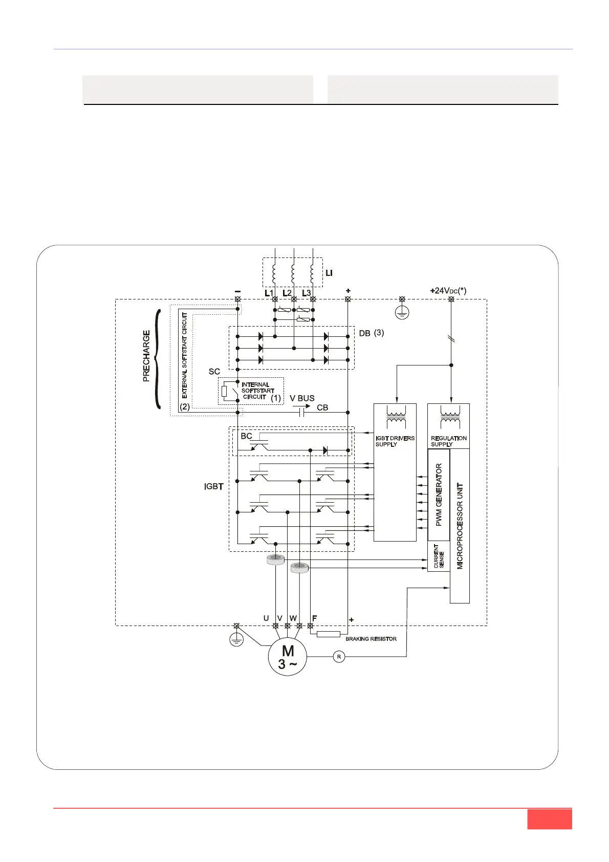
5.2.1- SESSIONE DI POTENZA
La tensione di rete applicata ai morsetti L1, L2, L3
(v. FIG. 9) viene raddrizzata dal ponte DB (per le taglie
OPDE 03A÷60A DB è un ponte a diodi, mentre per le
taglie OPDE 70A÷460A DB è un ponte semicontrollato
a diodi-tiristori) e filtrata dalla batteria di condensatori
CB. La tensione continua VBUS viene quindi modulata
da sei IGBT pilotati dalla scheda Driver gestita dal
microprocessore. U,V,W sono le fasi motore (tensione
PWM) (FIG. 9).
5.2.1- POWER STAGE
The mains voltage applied to terminals L1, L2, L3
(s. FIG. 9) is rectified by the rectifier bridge DB (for
sizes OPDE 03A÷60A DB is a diode bridge, whereas
for sizes OPDE 70A÷460A DB is a diode-thyristor semi
-controlled bridge rectifier) and is filtered by capacitor
bank CB. VBUS continuous voltage is modulated by
six IGBTs that are piloted by the microprocessor-
controlled Driver card. U,V,W are the motor phases
(PWM voltage) (FIG. 9).
FIG. 9 (Sessione di potenza / Power stage)
(*) Solo per modelli non autoalimentati/ Only for not autofeed products
(1) Solo per modelli OPDE 03A÷60A con tensione di ingresso AC e DC / Only for models OPDE 03A÷60A with AC and DC
input
(2) Solo per modelli OPDE 70A÷460A con tensione di ingresso DC e AC /Only for models OPDE 70A÷460A with DC and AC
input
(3) Nelle taglie 40A, 48A e 60A ,alimentati in DC e senza frenatura, non è presente / Is not present in the sizes 40A, 48A and
60A with DC power supply and without brake.