33
MP00000B00 V_2.6
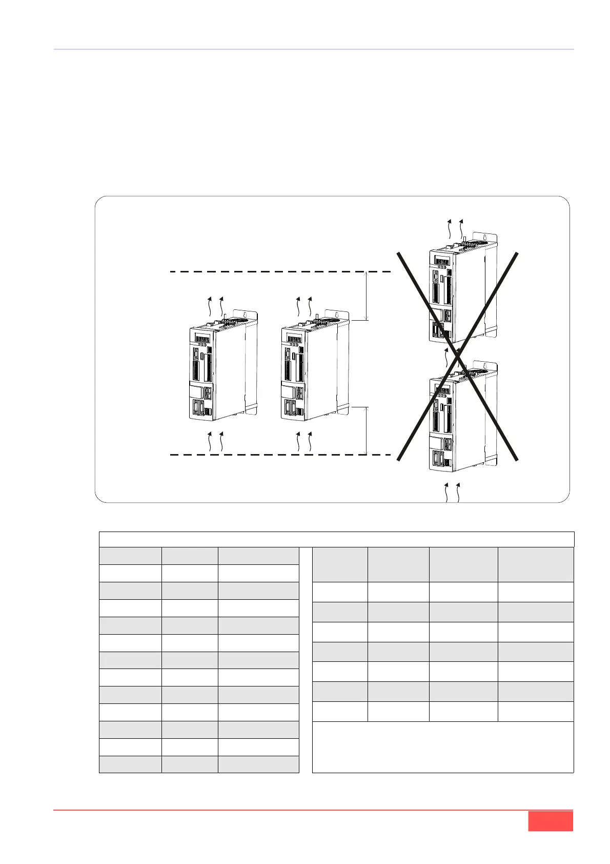
FIG. 5 (Installazione / Installation)
L’ambiente va eventualmente ventilato con sufficiente
quantità d’aria per asportare il calore generato dal con-
vertitore e dagli altri componenti.
Ulteriori apparecchiature vanno montate a distanza
sufficiente dall’azionamento onde evitare che possano
cadere all'interno di quest'ultimo dei residui metallici
derivati da foratura o da cavi elettrici.
If needed, provide sufficient air ventilation to remove
the heat generated by the converter and by other
components.
Any other equipment should be installed at a sufficient
distance from the drive, in order to prevent any metal
residues from drilling operations of from electric
cables from falling into the drive.
100 mm
150 mm
TAB. 7 (Potenza dissipata / Dissipated power)
Mod.
Watt
(DC
(3)
/AC)
Watt
(AC
(4)
/AC)
Aif flow (m3 / h)
150A
(1)
1500 1900 820
175A 1800 2200 820
220A 2200 2700 1080
250A 2450 3100 1080
310A 3000 3800 1620
370A 3600 4600 1620
460A
(2)
3500 4700 1620
(1)
Per il mod. 150A la PWM è 4kHz / For 150A mod. the PWM is 4kHz
(2)
Per il mod. 460A la PWM è 3kHz / For 460A mod. the PWM is 3kHz
(3)
Versione senza ponte raddrizatore / version without bridge rectifier
(4)
Versione con ponte raddrizatore / version with bridge rectifier
Mod. Watt Aif flow (m3 / h)
03A 80 30
07A 150 56
12A 250 79
15A 300 79
22A 400 112
32A 550 158
40A 650 168
48A 650 168
60A 700 180
70A 1200 308
90A 1400 360
110A 1800 460
Perdite a corrente nominale, Vin= 400 V, PWM= 5 KHz / Losses at rated current, Vin= 400 V, PWM= 5 KHz