65
MP00000B00 V_2.6
5.3.3 – ENCODER AND HALL
SENSORS
5.3.3 – ENCODER E SENSORE DI
HALL
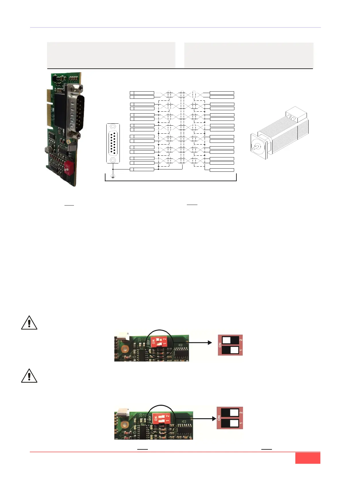
Only use 4-couples twisted and shielded couple cable
with external shield.
Encoder feed is 5V and its differential output has to be
“Line Driver”, with a number of pulses per revolution
that do not exceed 300KHz for channel at maximum
speed; current absorbed must not be above 100 mA.
Encoder feed can be different from 5V, up to 24V, in
that case the power supply has to be external. Con-
nect only drive pin 7 (GND) with external supply nega-
tive pole.
Usare solo cavo a doppini intrecciati e schermati sin-
golarmente più schermo esterno.
L’Encoder deve essere da 5V con uscita “Line Driver”,
con un numero di impulsi giro tali da non superare i
300KHz per canale; la corrente assorbita non deve
essere superiore ai 100mA.
L’ Encoder nel motore può essere anche ad una ten-
sione diversa da 5V (5÷24V). In tal caso deve essere
alimentato da una sorgente esterna. Collegare solo il
pin 7 dell’azionamento (GND) con il negativo di que-
sta sorgente.
8
+ 5V
7GND
/ PC1
3
11
PC1
2
10
/ PA1
PA1
9
1
PB1
/ PB1
SHIELD
15
4
12
13
5
6
14
SONDA_C
/ SONDA_B
SONDA_B
/ SONDA_A
SONDA_A
/ SONDA_C
GND
+ 5V
SONDA_C
/ SONDA_C
SONDA_A
/ SONDA_A
SONDA_B
/ SONDA_B
PC1
/ PC1
PA1
/ PA1
PB1
/ PB1
SHIELD
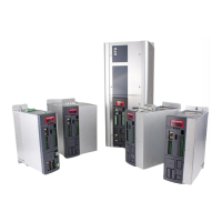
WARNING: for the encoder with internal supply
(standard drive version) you must connect the ter-
minal 8. Set the switch on the board as indicated in
the follow image (closed)
WARNING: for the encoder with external supply,
you must not connect the terminal 8 (+5V), because
it could seriously damage the drive. Set the switch
on the board as indicated in the follow image
ATTENZIONE: per gli encoder con alimentazione
interna (azionamento in versione standard) si deve
collegare il pin 8 (+5V) e posizionare il dip-switch
sulla scheda come riportato di seguito (chiuso)
ATTENZIONE: per gli encoder con alimentazione es-
terna non si deve collegare il pin 8 (+5V) , perchè
questo danneggerebbe gravemente l’azionamento.
Posizionare il dip-switch sulla scheda come riportato
di seguito (aperto)
-Cablare connettore femmina 15 vie
-Cabling 15-way connector female
COLLEGAMENTI CAVO DRIVE/MOTORE
DRIVE/MOTOR CABLE CONNECTIONS
cod. 274S001710VV
Qualsiasi manovra va effettuata solo a drive spento! / Any operation must be done only to drive off!