72
MP00000B00 V_2.6
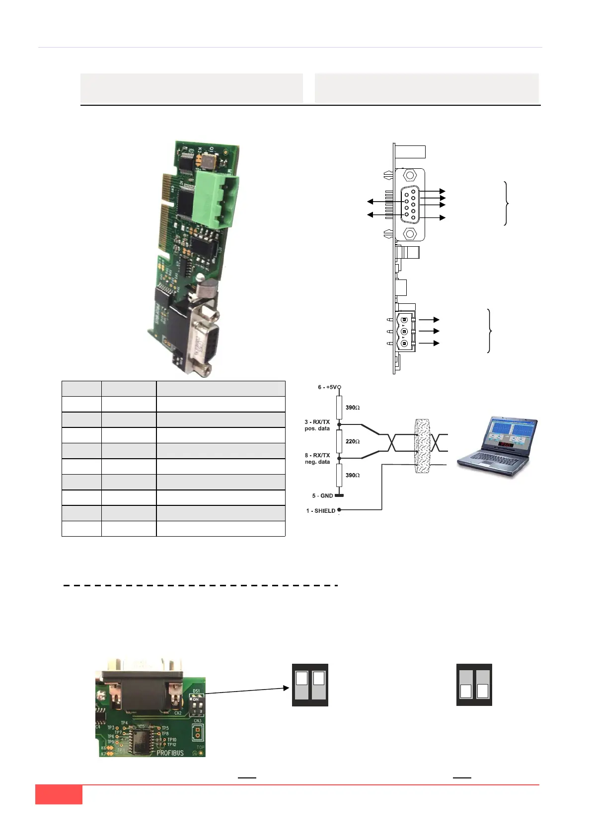
5.3.13 – PROFIBUS
Viene di seguito riportata la piedinatura della scheda
opzionale per la comunicazione via PROFIBUS - CAN
BUS
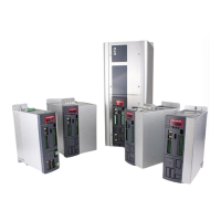
Sulla scheda è previsto un dipswitch doppio indicato
come DS1 che se chiuso connette il segnale CAN H e
CAN L mediante una resistenza da 120 per la termi-
nazione della linea.
5.3.13 – PROFIBUS
In the follow is indicated the pin signals position about
PROFIBUS - CAN BUS optional card
On the board are present a double dipswitch that
when closed connect the CAN H and CAN L signals
through a resistor (120) for termination of the line.
CAN L
GND
CAN BUS
CAN H
1) Shield
3) B
4) DE
5) GNDISO
6) +5VISO
8) A
PROFIBUS
Pin n. Name Descriptrion
1 Shield Protective shield
2 - -
3 B Rx/Tx positive data
4 DE Control’s signal for repeater
5 GNDISO 0V of supply
6 +5VISO Output supply +5V
7 - -
8 A Rx/Tx negative data
9 -
ON
1
2
Configurazione di default. Segnali CAN H
e CAN L terminati da resistenza 120.
Default setting. CAN H and CAN L si-
gnals terminated by (120) resistance.
ON
1
2
Segnali CAN H e CAN L non ter-
minati da resistenza.
CAN H and CAN L signals not
terminated by resistance.
TAB. 22 (Collegamenti Profibus / Profibus connections)
c
o
d
.
2
7
4
B0
0
0
2
2
0
VV
Qualsiasi manovra va effettuata solo a drive spento! / Any operation must be done only to drive off!
Solo parte CAN / Only CAN part
Terminazione profibus / Profibus termination