57
MP00000B00 V_2.6
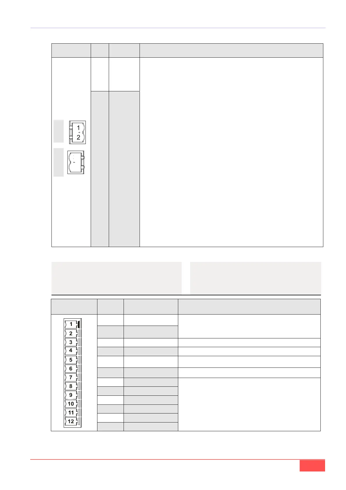
X3 PIN
FUNZIONE
FUNCTION
DESCRIZIONE / DESCRIPTION
1 +24V - IN
Tensione ausiliaria di alimentazione a +24V (±10%).
Auxiliary power supply +24V (±10%).
La corrente assorbita dall’OPDE sul +24V è:
The currents required from + 24V are as follows:
OPDE 03÷ 32A max. 1.0A
OPDE 40÷60A max. 1.6A
OPDE 70A÷ 460A max. 1.0A
Vedi par. 5.2.7, TAB. 3A, TAB. 3C
See par. 5.2.7,TAB. 3A, TAB. 3C
Attraverso i pin X3-1 ed X3-2 è possibile alimentare la logica di controllo ed il sensore
presente sul motore (necessaria per OPDE 03÷60A nella versione non autoalimenta-
ta).
Through the pins X3-1 and X3-2 is possible to power the control board and motor sen-
sor (mandatory for OPDE 03÷60A no autofeed.
L’OPDE 70÷460A genera al suo interno il +24V a partire dalla tensione di alimentazio-
ne principale.
Attraverso X3 è possibile alimentare la logica di controllo con un +24V esterno: la ten-
sione generata internamente e quella fornita dall’esterno non vanno in conflitto, ma
sarà impiegata la sorgente con il livello di tensione maggiore. Questo permette di:
a) parametrizzare il convertitore senza alimentare la parte di potenza
b) mantenere accesa la parte di controllo anche se manca l’alimentazione di po-
tenza.
The OPDE 70÷460A generates internally an auxiliary supply of +24V from the main
power supply.
The control board of OPDE can be fed through X3 with an external +24V: there aren't
conflict between the voltage generated internally and auxiliary supply provided exter-
nally. Infact is used the source with higher voltage level. This allows you to:
a) configure the drive without main power supply
b) keep alight the control part even if it lacks the main power supply.
2 0V
TAB. 12 (Alimentazioni / Supply)
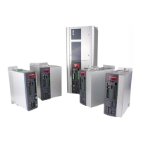
M4-X4 PIN
FUNZIONE
FUNCTION
DESCRIZIONE / DESCRIPTION
1 PTC Bimetallic
Ingresso sonda termica motore (PTC o NTC o KTY84).
Motor thermal probe input (PTC or NTC or KTY84).
2 /PTC Bimetallic
3 PE
4 N.C.
5 +Vcc Vmax= 27Vdc
6 GND
7 CHANNEL /C
8 CHANNEL C
9 CHANNEL /B
10 CHANNEL B
11 CHANNEL /A
12 CHANNEL A
Connessioni per Encoder Simulato
( vedi manuale utente par. “Segnali encoder simulato”)
Connection for Simulated Encoder
( see the user’s manual “Simulated encoder signals”)
5.2.15- GESTIONE SENSORE
TERMICO MOTORE ED EN-
CODER SIMULATO
5.2.15- MANAGEMENT OF MOTOR
THERMAL SENSOR AND
SIMULATED ENCODER
03A÷60A
70A÷460A
1
2
TAB. 13 (Gestione sensore termico motore ed encoder simulato / Management of motor thermal sensor and simulated encoder)