139
5.4
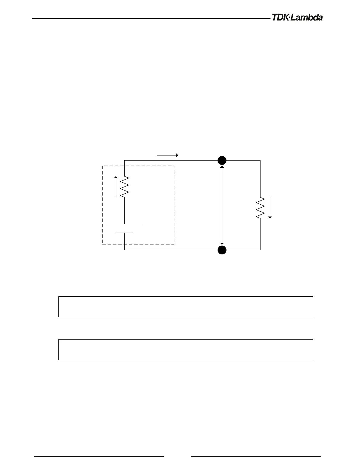
Internal Resistance
Internal resistance function is primarily used to simulate battery voltage drop, as a response to load
current. In addition, it can be used in cases of voltage drop over long load wires.
Power supply output voltage V
OUT
is set according to voltage setting minus actual load current
multiplied by internal resistance value setting (V
OUT
=V-I×R
S
).
Internal resistance function is enabled via the Front Panel menu (refer to section 1.8) or the
communication command SYSTem:RIN:STATe <Bool>.
Internal resistance setting range is 0.001 to 1 ohm, in steps of 0.001 ohms. Internal resistance
setting is available via the Front Panel menu (refer to section 1.8) or the communication command
SYSTem:RIN[:LEVel] <NRf+>.
OUT
V
L
R
S
R
V
Ideal
voltage
source
Internal
resistance
Battery
I
I
I
Figure 5–7: Internal Resistance Circuit
NOTE
If the Internal Resistance function is enabled, the Sequencer, Constant Power Limit, Slew-Rate
and Analog Programming functions are disabled.
NOTE
If the Sequencer, Constant Power Limit, Slew-Rate or Analog Programming functions are
enabled, the Internal Resistance function is disabled.