173
8.6
Troubleshooting
If the power supply appears to be operating improperly, use the Table 8-1 to determine whether the
power supply, load or external control circuits are the cause.
Configure the power supply for basic front panel operation and perform the tests listed in Safety &
Installation manual, Turn-On Checkout Procedure section to determine whether the problem can
be found with the power supply.
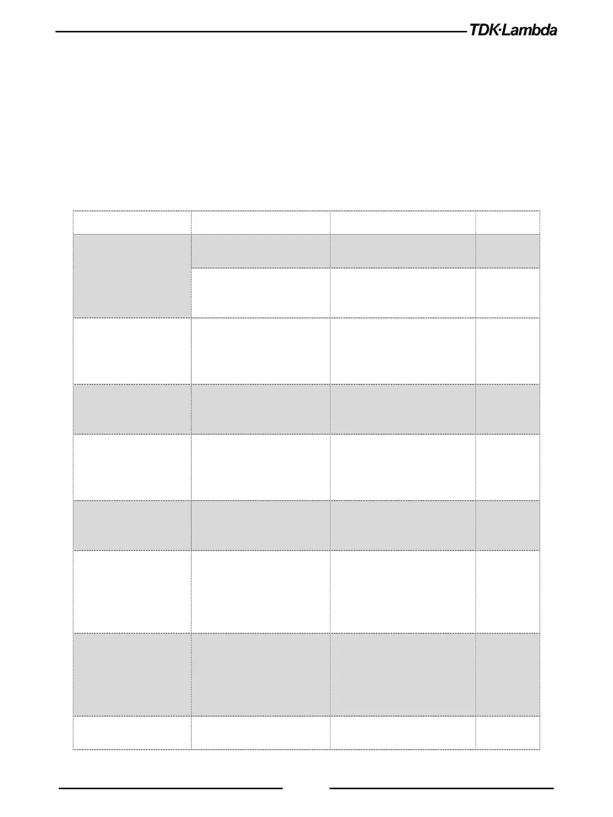
Table 8-1 provides the basic checks that can be performed to diagnose problems, and references
to relevant sections of this manual for further information.
No output. All displays and
indicators are blank.
Is the AC power cord defective? Check continuity and replace if
Installation
Is the AC input voltage within
range?
Check input AC voltage.
Connect to appropriate voltage
Installation
Manual (*)
Output is present
momentarily but shuts off
quickly. The display
AC FAULT
Does the AC source voltage sag
when load is applied?
Check input AC voltage.
Connect to appropriate voltage
source.
Installation
Manual (*)
Output voltage does not
adjust. Front panel CC
Is the unit in constant current
mode?
Check current settings and load
current.
2.9.6
Output voltage does not
adjust. Front panel CV
indicator is on.
Output voltage cannot be
adjusted above OVP setting or
below UVL setting via the Front
Set OVP or UVL not to limit the
output.
2.9.3
Output current does not
adjust. Front panel CV
Is the unit in constant voltage
mode?
Check the current and voltage
settings.
2.9.6
Large ripple present in
output.
Is the power supply in the
Remote sense? Is the voltage
drop on the load wire high?
Check load and sense wire
connections for noise and
impedance effects.
Minimize the drop on the load
Installation
Manual (*)
2.9
2.2
No
output. Display indicates
OVP
Over Voltage Protection circuit
has tripped.
Turn off the AC power to the unit.
Check load connections.
If analog programming is used,
check if the OVP is set lower than
No output. Display indicates SO Check if the rear panel J1 Output