Do you have a question about the Technica CM 100 High and is the answer not in the manual?
Describes the CM_100_High's capabilities and technical specifications for traffic capture.
Provides essential safety precautions and warranty terms for operating the device.
Official document stating the device meets EU directives for electromagnetic compatibility.
Lists the items included in the product package and optional accessories.
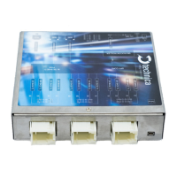
Describes all physical connectors, including MQS and RJ45, with pinning information.
Explains the frontside black MQS connector for power supply and wake-up lines.
Details the three Gigabit Ethernet RJ45 ports for logging and synchronization.
Describes the backside white MQS connectors and their pin assignments.
Describes the Micro HDMI interface used for programming and debugging purposes.
Covers interfaces beyond standard connectors, like the rotary switch.
Explains the rotary switch for manual IP address configuration.
Details IP address configuration via rotary switch positions 0 through D.
Explains how IP address is configurable via System Information tab at rotary switch position E.
Describes the non-configurable IP address at rotary switch position F and reset behavior.
Explains the meaning of the status LEDs located on the front of the device.
Guides users on how to access the device's web interface for configuration and monitoring.
Explains how to save configuration changes and restart the device if needed.
Describes the initial home screen of the web interface and its navigation tabs.
Details how to view device status, firmware versions, and hardware information via the System Information tab.
Presents detailed general status and version information of the CM_100_High device.
Explains how to view and change the device's IP addresses via the web interface.
Introduces the Control Panel tab for importing/exporting configurations and general settings.
Describes the function of the restart button to reboot the CM_100_High.
Details how to manage configuration files, including naming and saving.
Explains how to prevent the device from entering sleep mode and its operational modes.
Defines the conditions under which the CM_100_High remains active and does not enter sleep mode.
Describes how the device can be woken up from sleep mode using specific wake-up lines.
Details the configuration and functionality of the device's wake-up lines as input or output.
Sets the time in seconds before the actuator of wake-up lines is set to ground.
Defines the time in seconds before the device enters sleep mode due to inactivity.
Allows setting the device's date and time for accurate timestamping in protocols.
Provides an overview of the link status for all ports on the device.
Configures logging parameters and sets up filters for traffic capture.
Controls the encapsulation of logged data within a PLP-protocol header.
Manages traffic shaping and sets the maximum bandwidth for data transmission.
Determines if VLAN IDs from original frames are carried over to the PLP header.
Allows logging packets with outer VLAN tags without PLP header encapsulation.
Configures the MAC destination address for the PLP-protocol header.
Controls packetization of logged frames and sets the timeout for this process.
Defines which ports are used for packetization and limits to one port at a time.
Sets the delay before logged data is sent after power on or wakeup.
Provides an overview of basic filters and access to edit them.
Allows users to apply and edit basic filters for captured data.
Enables the creation and management of advanced filters for traffic capture.
Configures the 100BASE-T1 port for host communication, including BroadR-Reach mode.
Details Gigabit Ethernet ports used for logging and time synchronization between modules.
Explains the configuration of 100BASE-T1 ports for logging and injection.
Describes how to synchronize multiple devices using the 802.1AS PTP protocol.
Details how time-synchronization information is transported via Sync and Follow Up messages.
Explains the process of measuring propagation delay for accurate time synchronization.
Provides guidance on setting up a synchronized network using CaptureModules.
Details advanced filtering rules for packet capture and manipulation.
Explains the capabilities and limitations of creating advance filter rules.
Demonstrates how to configure an advance filter to drop specific frames based on VLAN and IP.
Guides on injecting traffic to a connected device (DUT) through the logging port.
Lists essential prerequisites and critical information before performing a firmware update.
Step-by-step instructions for updating the device firmware using the GB-A port.
Details the procedure for updating firmware via the 100BASE-T1 port using a MediaConverter or Gateway.
| Brand | Technica |
|---|---|
| Model | CM 100 High |
| Category | Control Unit |
| Language | English |