7 LIST OF FIGURES
Figure 1-1: Chapture_Module_100_High ........................................................................... 5
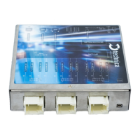
Figure 1-2: Capture_Module_100_High ............................................................................. 5
Figure 1-3: Copy of Declaration of conformity ................................................................. 8
Figure 2-1: Label of CM_100_High with pinning information .......................................... 9
Figure 2-2: Power Connector ........................................................................................... 10
Figure 2-3: RJ45 Connectors ........................................................................................... 11
Figure 2-4: 3x White MQS Connectors backside ............................................................ 11
Figure 2-5: Debug Connector ........................................................................................... 13
Figure 2-6: LED allotment on front of the device ............................................................ 14
Figure 3-1: Home Screen CM_100_High ......................................................................... 16
Figure 4-1: Save Configuration ........................................................................................ 17
Figure 4-2: CM_100_High Home Screen ......................................................................... 17
Figure 4-3: System Information tab ................................................................................. 18
Figure 4-4: IP-addresses ................................................................................................... 20
Figure 4-5: Control Panel .................................................................................................. 21
Figure 4-6: Restart device ................................................................................................. 22
Figure 4-7: Handling of configuration files ..................................................................... 22
Figure 4-8: Download windows ........................................................................................ 23
Figure 4-9 Settings for Prevent Sleep .............................................................................. 24
Figure 4-10: WakeUp lines ................................................................................................ 25
Figure 4-11: WUP time to LOW ........................................................................................ 26
Figure 4-12: Sleep Timeout .............................................................................................. 26
Figure 4-13: Date and Time .............................................................................................. 27
Figure 4-14: Switch Status tab ......................................................................................... 28
Figure 4-15: Spy multiplexer............................................................................................. 29
Figure 4-16: Overview Filters Table ................................................................................. 32
Figure 4-17: Filters Table .................................................................................................. 33
Figure 4-18: User interface advanced filter ..................................................................... 34
Figure 4-19: Host Port ...................................................................................................... 37
Figure 4-20: GB-A Port ...................................................................................................... 38
Figure 4-21: OABR-Ports ................................................................................................... 40
Figure 4-22: 802.1AS PTP bridge .................................................................................... 42
Figure 4-23: P-Delay .......................................................................................................... 43
Figure 4-24: Example Advance Filter Drop ...................................................................... 44
Figure 4-25: Example test setup for inject ...................................................................... 45
Figure 4-26: Example for IP Injection .............................................................................. 45
Figure 4-27: Example for IP Injection .............................................................................. 46
Figure 4-28: Filter of our example for IP Injection .......................................................... 46
Figure 5-1: Update on GB-Port ......................................................................................... 48
Figure 5-2: left side update with MediaConverter, right side update with MediaGateway
............................................................................................................................................ 49
 Loading...