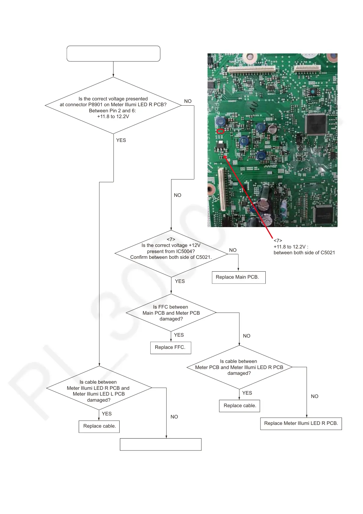
7.6. Meter Illumination - No Light
No Meter Illumination.
YES
Is the correct voltage presented
at connector P8901 on Meter Illumi LED R PCB?
Between Pin 2 and 6:
+11.8 to 12.2V
Replace Meter Illumi LED R PCB.
Is cable between
Meter PCB and Meter Illumi LED R PCB
damaged?
YES
Replace cable.
NO
Is FFC between
Main PCB and Meter PCB
damaged?
YES
Replace FFC.
NO
NO
<7>
Is the correct voltage +12V
present from IC5004?
Confirm between both side of C5021.
Replace Main PCB.
Main PCB
<7>
+11.8 to 12.2V :
between both side of C5021
NO
NO
YES
Replace Meter Illumi LED L PCB.
Is cable between
Meter Illumi LED R PCB and
Meter Illumi LED L PCB
damaged?
YES
Replace cable.
NO