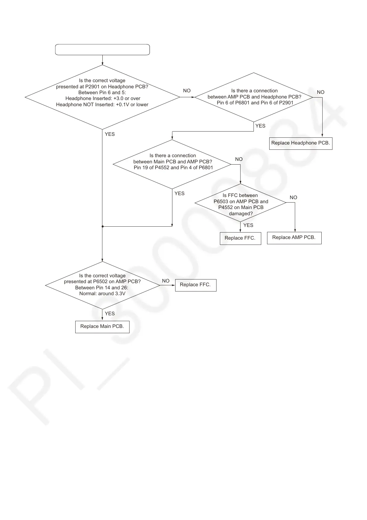
7.13. No Sound from Headphone
Is there a connection
between AMP PCB and Headphone PCB?
Pin 6 of P6801 and Pin 6 of P2901
Is the correct voltage
presented at P6502 on AMP PCB?
Between Pin 14 and 26:
Normal: around 3.3V
Replace Main PCB.
YES
No Sound from Headphone.
Is the correct voltage
presented at P2901 on Headphone PCB?
Between Pin 6 and 5:
Headphone Inserted: +3.0 or over
Headphone NOT Inserted: +0.1V or lower
NO
Replace Headphone PCB.
YES
NO
Is there a connection
between Main PCB and AMP PCB?
Pin 19 of P4552 and Pin 4 of P6801
YES
YES
Replace FFC.
Is FFC between
P6503 on AMP PCB and
P4552 on Main PCB
damaged?
YES
Replace AMP PCB.
Replace FFC.
NO
NO
NO